PWM output problem (stopping the signal)
Discussion in "8051 Discussion Forum" started by neil03 Aug 6, 2009.


Thu Aug 06 2009, 01:03 am
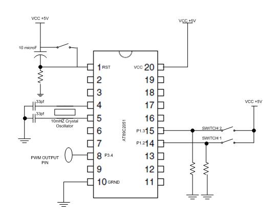
hi im working on a PWM signal output from a microcontroller using at89c2051.
The status of my project is that I successfully produce the desired PWM signal but, my problem is I cannot stop the process of stopping the PWM signal when I switch it to stop.
____________________________________________________________________
The algorithm of the program is simply like this
1. when switch 1 is pressed the microcontroller produce a PWM signal
2. when switch 2 is pressed the micrcontroller stop producing the signal or clearing the output pin of the MC.
____________________________________________________________________
Now as I have said above I successfully produce the desired PWM signal but when I switch it to stop. The PWM output pin remains to produce the PWM signal..Honestly this program is really working previously and I have used this program several times ago but now when I try to burn it on a new microcontroller it doesnt respond to its previous state.. I also try to change different at89c2051, 3 mc to be exact, but still im getting the same problem..
Im thinking that the maybe the programmer have a defect or something, but im not so sure and I dont want to take the risk of buying a new programmer cause it costs alot.
Can anybody help me to find what is the problem causing this and please teach me to resolve it..I have attach the program and the schematic of my project. please help me people thank you so much.
![]()
The status of my project is that I successfully produce the desired PWM signal but, my problem is I cannot stop the process of stopping the PWM signal when I switch it to stop.
____________________________________________________________________
The algorithm of the program is simply like this
1. when switch 1 is pressed the microcontroller produce a PWM signal
2. when switch 2 is pressed the micrcontroller stop producing the signal or clearing the output pin of the MC.
____________________________________________________________________
Now as I have said above I successfully produce the desired PWM signal but when I switch it to stop. The PWM output pin remains to produce the PWM signal..Honestly this program is really working previously and I have used this program several times ago but now when I try to burn it on a new microcontroller it doesnt respond to its previous state.. I also try to change different at89c2051, 3 mc to be exact, but still im getting the same problem..
Im thinking that the maybe the programmer have a defect or something, but im not so sure and I dont want to take the risk of buying a new programmer cause it costs alot.
Can anybody help me to find what is the problem causing this and please teach me to resolve it..I have attach the program and the schematic of my project. please help me people thank you so much.
 switch1   EQU P1.2     ; switch for PWM
 switch2   EQU P1.3		; switch for stop PWM signal
 PWMPIN    EQU P3.4      ; PWM output pin

ORG 00H
SJMP Main

org 0BH ;Vector address for Timer0
AJMP TIMER_0_INTERRUPT ;jump to ISR routine

;Main code
Main:
JB  P1.2, PWM_INI ; go to PWM setting 1
sjmp Main

PWM_INI:         ;initiate PWM
acall PWM_SETUP
here:
JB   P1.3, STOP;
SJMP here ;

STOP:
clr PWMPIN
sjmp Main;


PWM_SETUP:
        MOV TMOD,#00H           ; Timer0 in Mode 0
        MOV R7, #240            ; Set pulse width control
        ; The value loaded in R7 is value X as
        ; discussed above.
        SETB EA         ; Enable Interrupts
        SETB ET0                ; Enable Timer 0 Interrupt
        SETB TR0                ; Start Timer
        RET

TIMER_0_INTERRUPT:
        JB F0, HIGH_DONE        ; If F0 flag is set then we just finished
                                ; the high section of the
LOW_DONE:                       ; cycle so Jump to HIGH_DONE
        SETB F0                 ; Make F0=1 to indicate start of high section
        SETB PWMPIN             ; Make PWM output pin High
        MOV A, #0FFH            ; Move FFH (255) to A
        CLR C                   ; Clear C (the carry bit) so it does
                                 ; not affect the subtraction
        SUBB A, R7              ; Subtract R7 from A. A = 255 - R7.
        MOV TH0, A              ; so the value loaded into TH0 + R7 = 255
		CLR TF0                 ; Clear the Timer 0 interrupt flag
        RETI                    ; Return from Interrupt to where
                                        ; the program came from
HIGH_DONE:
        CLR F0                  ; Make F0=0 to indicate start of low section
        CLR PWMPIN              ; Make PWM output pin low
        MOV TH0, R7             ; Load high byte of timer with R7
                                ; (pulse width control value)
        CLR TF0                 ; Clear the Timer 0 interrupt flag
        RETI                    ; Return from Interrupt to where
                                ; the program came from


END
[ Edited Thu Aug 06 2009, 01:05 am ]


Thu Aug 06 2009, 01:21 am
well schematic is not so big to have a problem in it.
You can load a simple LED blink program to see if your controller is fine or not.
I think problem seems to be in program for making it non stop PWM. the reason is.. PWM works with timer so along with clearing of PWM pin, you should also clear TR0, and TF0 so that timer stops and interrupt flags can be cleared. and to start PWM again, you have the init function.
[Topic moved to 8051 Discussion forum]
You can load a simple LED blink program to see if your controller is fine or not.
I think problem seems to be in program for making it non stop PWM. the reason is.. PWM works with timer
so along with clearing of PWM pin, you should also clear TR0, and TF0 so that timer stops and interrupt flags can be cleared. and to start PWM again, you have the init function.[Topic moved to 8051 Discussion forum]


Thu Aug 06 2009, 07:37 am
You'll also have to make sure the SW1 switch is off else the pwm generation will start again.
better implement sth like this....
better implement sth like this....
Main:
JNB  P1.2, Main;check if START is pressed
JNB P1.3,PWM_INI ; go to PWM setting 1 if STOP not pressed
sjmp Main
Powered by e107 Forum System

ztaletpzca
Wed Apr 24 2024, 11:19 pm

IrardlPex
Wed Apr 24 2024, 08:42 pm

Charlestehed
Wed Apr 24 2024, 05:20 pm

Robertgurse
Wed Apr 24 2024, 02:43 pm

Richardedils
Wed Apr 24 2024, 04:07 am

Malcolmaccek
Wed Apr 24 2024, 01:21 am

ChrisLub
Tue Apr 23 2024, 05:21 pm

Davidbab
Tue Apr 23 2024, 10:41 am