Current measurement circuit
Discussion in "Electronics" started by MPU_Beginner Apr 12, 2011.


Tue Apr 12 2011, 02:50 pm
Hey,
I need to design a circuit to measure the current consumption of my uP using a current shunt monitor. I have already chosen the current shunt monitor which offers a very large common mode range. The current i want to measure is 1uA ... 100 mA. Then the analog values have to be forwarded to an ADC etc...
Any proposals?


Tue Apr 12 2011, 11:07 pm
Hey,
I need to design a circuit to measure the current consumption of my uP using a current shunt monitor. I have already chosen the current shunt monitor which offers a very large common mode range. The current i want to measure is 1uA ... 100 mA. Then the analog values have to be forwarded to an ADC etc...
Any proposals?MPU_Beginner
1uA ... 100 mA is a very wide range, too wide for a simple ADC.
What current shunt monitor are you using ?


Tue Apr 12 2011, 11:26 pm
I also used the same circuit of a transimpedance apmlfr ,
i got a very stable output on op-amp
I m facing problems in ADC
when I interfaced op-amp with ADC ,i am getting horribe fluctuations .The
ADC value jumps over a big range .even when the input which is output from opamp is stable.
please help ...
i got a very stable output on op-amp
I m facing problems in ADC
when I interfaced op-amp with ADC ,i am getting horribe fluctuations .The
ADC value jumps over a big range .even when the input which is output from opamp is stable.
please help ...
Wed Apr 13 2011, 02:05 pm
@rumman89: how does your circuit look like? Which ADC and aamplfr do u use?
I thought about using TINA213 from Texas Instruments... The problem is, using a single shunt resistor will never be sufficient to cover the whole current range...
I'm using a 12 bit ADC with 2,5V ref voltage...
how can I decide for the shunt resistor value/values?!
thx
I thought about using TINA213 from Texas Instruments... The problem is, using a single shunt resistor will never be sufficient to cover the whole current range...
I'm using a 12 bit ADC with 2,5V ref voltage...
how can I decide for the shunt resistor value/values?!
thx
Wed Apr 13 2011, 05:02 pm
here is the circuit ...
I used simple op-amp 741 and 1 one mega ohm resistr
actually it depends on the range of current you want to measure ,,
just remember the formula ...
V(output voltg.)=R*I
where 'R' is the feedback res. u use
and 'I' is the input current
I used simple op-amp 741 and 1 one mega ohm resistr
actually it depends on the range of current you want to measure ,,
just remember the formula ...
V(output voltg.)=R*I
where 'R' is the feedback res. u use
and 'I' is the input current
Thu Apr 14 2011, 02:17 pm
sorry but I did not really get it, how u connect your circuit to the uP.
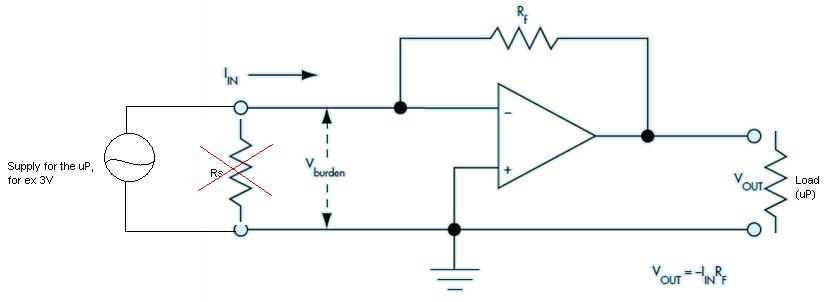
Please see my circuit attached, is that what you mean?
Thanks!
![]()
Please see my circuit attached, is that what you mean?
Thanks!
Thu Apr 14 2011, 09:18 pm
ok ,,u said your currnet range is from 1uA ... ,,ryt ?? ,,
then try a resistor of 2 to 3 mega ohms ,,you should get an output from
2 to 3 vlts according to the formula ,,
but make sure that current flows from right to left ,,(opposite to the direction shown in your diagram) to get a +ve output vltg ,as the op-amp is used in inverting mode.
then try a resistor of 2 to 3 mega ohms ,,you should get an output from
2 to 3 vlts according to the formula ,,
but make sure that current flows from right to left ,,(opposite to the direction shown in your diagram) to get a +ve output vltg ,as the op-amp is used in inverting mode.
Thu Apr 14 2011, 09:21 pm
One important thing after getting the gain is,, "stabilibty" of the circuit,
a feedback capacitor must be connected in parallel with the feedback resistor to gain stability ,,even I am workin on it to find the value of the capacitor.
I will tell it later ,,first you try to get the required output vltg ...
a feedback capacitor must be connected in parallel with the feedback resistor to gain stability ,,even I am workin on it to find the value of the capacitor.
I will tell it later ,,first you try to get the required output vltg ...
Thu Apr 14 2011, 09:23 pm
Do u think that the way shown in my diagramm is correct?! To which pin of the uP will u connect the Amp?
I thought I will connect it to the supply voltage pin, BUT the way shown in my diagramm the input voltage of the uP is different from the voltage given by the source (3V)!
I thought I will connect it to the supply voltage pin, BUT the way shown in my diagramm the input voltage of the uP is different from the voltage given by the source (3V)!
Powered by e107 Forum System

Richardedils
Wed Apr 24 2024, 04:07 am

ChrisLub
Tue Apr 23 2024, 05:21 pm

Davidbab
Tue Apr 23 2024, 10:41 am

Richardrit
Tue Apr 23 2024, 09:54 am

HenryLaf
Mon Apr 22 2024, 03:50 pm

bleradrar
Mon Apr 22 2024, 06:38 am

ppu-pro_ka
Sun Apr 21 2024, 07:39 pm

Infewow
Sun Apr 21 2024, 06:30 pm