Interfacing LDR with 8051
Discussion in "8051 Discussion Forum" started by SkyTerror17 Sep 26, 2011.


Tue Oct 04 2011, 01:10 pm
Yeah, I saw that website, its really useful.
But I am required to use a single supply op amp and no relay.
Is there anyway to test a schematic using some software program or something?
But I am required to use a single supply op amp and no relay.
Is there anyway to test a schematic using some software program or something?
[ Edited Tue Oct 04 2011, 01:46 pm ]


Tue Oct 04 2011, 03:48 pm
@ SkyTerror17
u can operate that circuit with 5 volt
12 volt is for relay
replace a relay and diode with 10k resistor and get logic on the collector of transistor
u can operate that circuit with 5 volt
12 volt is for relay
replace a relay and diode with 10k resistor and get logic on the collector of transistor
Wed Oct 05 2011, 07:09 am
Just asking, what if my power supply is single supply? Does it still works?
[ Edited Wed Oct 05 2011, 07:41 am ]
Wed Oct 05 2011, 10:12 am
@ SkyTerror17
in normal cases single power supply is need connect (-) in schematic to ground and (+) to 5 volt nothing else
in normal cases single power supply is need connect (-) in schematic to ground and (+) to 5 volt nothing else
Wed Oct 05 2011, 10:54 am
Yah, I was alittle confused on that part. I did a schematic and place the components on the breadboard to test it out, still troubleshooting!
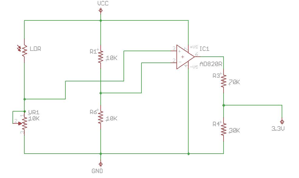
The pic below is a new schematic that I just made. I intend to have a 3.3V at the output when LDR is covered (dark) but still having some problems with the output voltage.
![]()
The pic below is a new schematic that I just made. I intend to have a 3.3V at the output when LDR is covered (dark) but still having some problems with the output voltage.
Wed Oct 05 2011, 01:23 pm
@ SkyTerror17
what is the problem u just to tune some values nothing else it should work
what is the problem u just to tune some values nothing else it should work


Wed Oct 05 2011, 09:26 pm
I intend to have a 3.3V at the output when LDR is covered.SkyTerror17
Your setup will be low when the LDR is covered.
Either reverse Vr1 and the LDR or reverse the inputs to the op-amp.
Why drop the output to 3.3 volts ?
R3 and R4 are the wrong way round, and I would use lower values for each.
Wed Oct 05 2011, 09:57 pm
@majoka
Yeah, everything is almost done. I just have to tune the values of the resistor for R3 and R4 to reach the output voltage that I want!
@ExperimenterUK
Yeah, I swapped the LDR and VR1.
So does the R3 and R4, I even changed the values to 1k for R3 while 10k for R4.
Apologies as my group-mate got the concept wrongly!
We need to drop the output to 3.3V because our 8051 runs on 3.3V.
And we are gonna send a high or low input to it.
Thu Oct 06 2011, 01:18 am
So does the R3 and R4, I even changed the values to 1k for R3 while 10k for R4.SkyTerror17
10k is too high ..
1k and 1.8k would be better.
Powered by e107 Forum System

Robertrip
Fri Apr 26 2024, 11:20 am

ArnoldDiant
Fri Apr 26 2024, 03:53 am

RodneyKnorb
Thu Apr 25 2024, 07:08 pm

Williamjef
Thu Apr 25 2024, 02:08 pm

SamuelSmise
Thu Apr 25 2024, 09:56 am

DustinErele
Thu Apr 25 2024, 08:44 am

ztaletpzca
Wed Apr 24 2024, 11:19 pm

IrardlPex
Wed Apr 24 2024, 08:42 pm