query regarding seven segment display


Wed May 21 2008, 08:30 am
thanx sir,i'll try 2 correct my connection.sir,i have tried 2 correct my program codeiam enclosing it once more,the problem is that when i simulate my program at port p1 it only shows 2 digits 3f and 06.if i add the instruction MOV P1,#00h after every displayin order to clear the displays ,when i connect my circuit 7-segment only displays 8 and 0.please sir help me out of this problem
setb p2.5
setb p2.6
intr bit p2.7
setb intr
adc_port equ p1
adc_val equ 30h
voltage_val equ r3
org 0h
start: acall read
acall conversion
mov a,adc_val
sjmp start
conversion: clr wr
setb wr
read: clr rd
mov a,adc_val
setb rd
mov r3,#00h
mov a,#00h
cjne a,#00,over1
over1: acall data_display1
mov r3,#01h
mov a,#33h
cjne a,#51,over2
over2: acall data_display2
mov r3,#02h;
mov a,#67h;
cjne a,#103,over3
over3: acall data_display3
mov r3,#03h
mov a,#97h
cjne a,#151,over4
over4: acall data_display4
mov r3,#04h
mov a,#99h
cjne a,#153,over5
over5: acall data_display5
mov r3,#05h
mov a,#0ffh
cjne a,#255,over6
over6: acall data_display6
data_display1: mov a,#00h
mov b,#0ah
div ab
mov r7,b
mov b,#0ah
div ab
mov r6,b
mov r5,a
mov a,r7
acall disp_sevensegment
acall delay
mov a,r6
acall disp_sevensegment
acall delay
mov a,r5
acall disp_sevensegment
acall delay
ret
data_display2: mov a,#33h
mov b,#0ah
div ab
mov r7,b
mov b,#0ah
div ab
mov r6,b
mov r5,a
mov a,r7
acall disp_sevensegment
acall delay
mov a,r6
acall disp_sevensegment
acall delay
mov a,r5
acall disp_sevensegment
acall delay
ret
data_display3: mov a,#67h
mov b,#0ah
div ab
mov r7,b
mov b,#0ah
div ab
mov r6,b
mov r5,a
mov a,r7
acall disp_sevensegment
acall delay
mov a,r6
acall disp_sevensegment
acall delay
mov a,r5
acall disp_sevensegment
acall delay
ret
data_display4: mov a,#97h
mov b,#0ah
div ab
mov r7,b
mov b,#0ah
div ab
mov r6,b
mov r5,a
mov a,r7
acall disp_sevensegment
acall delay
mov a,r6
acall disp_sevensegment
acall delay
mov a,r5
acall disp_sevensegment
acall delay
ret
data_display5: mov a,#99h
mov b,#0ah
div ab
mov r7,b
mov b,#0ah
div ab
mov r6,b
mov r5,a
mov a,r7
acall disp_sevensegment
acall delay
mov a,r6
acall disp_sevensegment
acall delay
mov a,r5
acall disp_sevensegment
acall delay
ret
data_display6: mov a,#0ffh
mov b,#0ah
div ab
mov r7,b
mov b,#0ah
div ab
mov r6,b
mov r5,a
mov a,r7
acall disp_sevensegment
acall delay
mov a,r6
acall disp_sevensegment
acall delay
mov a,r5
acall disp_sevensegment
acall delay
ret
disp_sevensegment: cjne a,#0,d1
mov p1,#03fh
acall delay
d1: cjne a,#1,d2
mov p1,#06h
d2: cjne a,#2,d3
mov p1,#05bh
d3: cjne a,#3,d4
mov p1,#04fh
d4: cjne a,#4,d5
mov p1,#066h
d5: cjne a,#5,d6
mov p1,#06dh
d6: cjne a,#6,d7
mov p1,#7dh
d7: cjne a,#7,d8
mov p1,#07h
d8: cjne a,#8,d9
mov p1,#07fh
d9: cjne a,#9,d10
d10: mov p1,#067h
delay: mov r4,#200
here: djnz r4,here
ret
end
it has been a very lengthy post,please sir excuse me for this.
Wed May 21 2008, 08:44 am
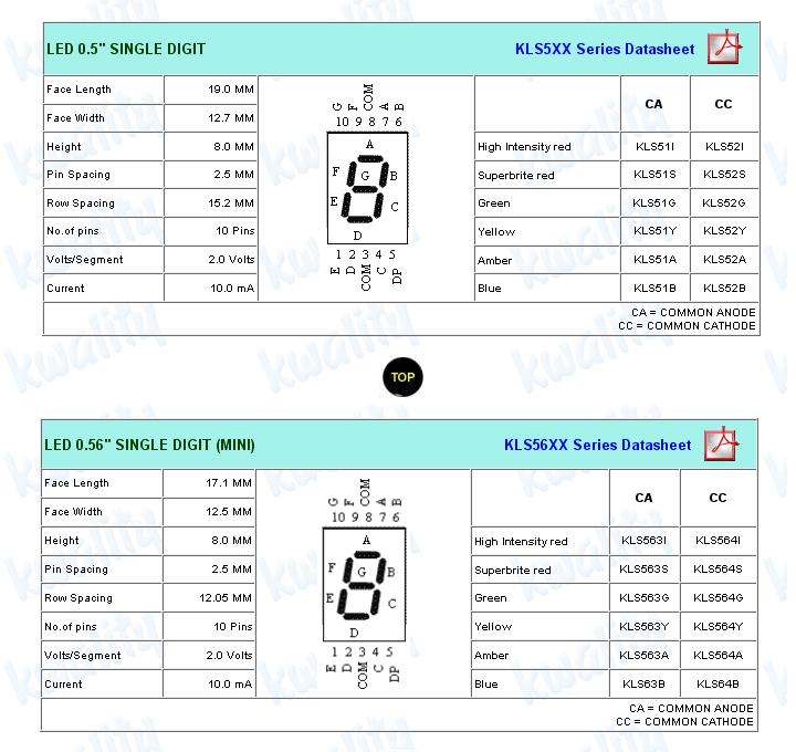
sir,can u please provide me a brief description of the chip SP5501(common anode) or give me any link where i can get its detailed datasheet.
thanking u.
thanking u.


Wed May 21 2008, 01:17 pm
the pin/segment configuration is same for both SP5501 and SP5503 but the difference is in Pin 3 & 8, they connect to Ground in SP5503 and to V+ in SP5501
My advice is to separate the ADC and Display to two ports, use ADC on port 3 and Display on port 1 or any free 8 bit port, do this first and make changes in the code
Arun
priya123 like this.
Thu May 22 2008, 09:45 am
sir,please tell me where i can find the datasheet of SP5501 or please givemethe datasheet of any other chip equivalent tio that.i had gone through the site www.kwalityindia.com but i am unable to understand datasheet of which chip wil be equivalent to SP5501.please help.


Tue May 27 2008, 07:40 am
thanx a lot pdi33 sir,my project is still not working as arun sir suggested I have connected the seven-segment display to a separate port P3 and have connected ADC at P1 of microcontroller but still seven-segment display doesn't show proper results,it first shows 8 then 0 .It is not functioning according to the logic of my program,please helpme out sir.
thanking u.
thanking u.
Tue May 27 2008, 01:12 pm
Hello Priya,
i appreciate your "Never Give up" attitude, i think the whole code is unnecessarily made complicated, here is my function steps to display 000 to 255 for voltage between 0-5 volts:
1) wire the ADC in free running mode
2) read ADC value from a port
3) call BIN2DEC routine to convert the ADC (Bin value) to Decimal value and store in three locations in RAM- Hundreds,tens,ones
4) Call Seven segment display routine - display 1st digit,2nd digit,3rd digit
here even if Acc is 0 or not equal to 0, micro jumps to Over1. can you tell me what this routine does?
how many 7 seg leds (digits) have you connected - single, two or three
give me the full details and i'll help you write the code here itself in the forum step by step
your Circuit diagram would be appreciated
one more thing, why are you confusing yourself and us by using Hex value sometimes and Decimal value sometimes
for eg : you instr. :
mov r3,#67h
cjne a,#103
use either Hex or Decimal notation for these camparisions
Arun
i appreciate your "Never Give up" attitude, i think the whole code is unnecessarily made complicated, here is my function steps to display 000 to 255 for voltage between 0-5 volts:
1) wire the ADC in free running mode
2) read ADC value from a port
3) call BIN2DEC routine to convert the ADC (Bin value) to Decimal value and store in three locations in RAM- Hundreds,tens,ones
4) Call Seven segment display routine - display 1st digit,2nd digit,3rd digit
mov r3,#00h
mov a,#00h
cjne a,#00,over1
over1: acall data_display1
here even if Acc is 0 or not equal to 0, micro jumps to Over1. can you tell me what this routine does?
how many 7 seg leds (digits) have you connected - single, two or three
give me the full details and i'll help you write the code here itself in the forum step by step
your Circuit diagram would be appreciated
one more thing, why are you confusing yourself and us by using Hex value sometimes and Decimal value sometimes
for eg : you instr. :
mov r3,#67h
cjne a,#103
use either Hex or Decimal notation for these camparisions
Arun
[ Edited Tue May 27 2008, 01:19 pm ]
priya123 like this.
Wed May 28 2008, 04:21 am
sir, in this project I am using a single seven-segment display,and in the earlier posts I have given the description of my entire circuit connection.
Wed May 28 2008, 07:25 am
Hello priya,
to help you out from frustration, here is my code, i hope this solves your problem,
stick to the comments in the program and rewire your connections if needded.
tell me if you need any other changes, ideally i would display ADC value in Hex to BCD
( 000-255 ) on three 7 seg displays, but you are using single display and your logic is different
i have tested the code on my trainer board and simulator and it works as intended !
: code deleted by Arun
Arun
[ Edited Tue Jul 15 2008, 02:12 pm ]
Wed Jun 04 2008, 04:58 am
thanx arun sir 4r ur code ,it helped me a lot but the fact is that it is not totally according to my circuit .I havementioned the logic of the program in the earlier posts.My problem is that the program code which I have written is simulated properly but when i am loading it onto the microcontroller chip and designing the entire circuit on the breadboard the seven-segment display does'nt work according to the circuit.ihave mentioned the circuit connections in the earlier posts.i am posting my program code .please help me to correct it tomake my circuit work.
setb p2.5
setb p2.6
intr bit p2.7
setb intr
adc_port equ p1
voltage_val equ r3
adc_val equ 30h
sevensegment_display equ p3
sevensegment_val equ 19h
org 0h
start: acall read_adc
acall conversion
mov p1,adc_val
sjmp start
conversion: clr wr
setb wr
read_adc: clr rd
mov a,p1
setb rd
mov r3,#01h
acall data_display1
mov r3,#02h
acall data_display2
mov r3,#03h
acall data_display3
mov r3,#04h
acall data_display4
mov r3,#05h
acall data_display5
data_display1: mov a,#33h
mov b,#0ah
div ab
mov r7,b
mov b,#0ah
div ab
mov r6,b
mov r5,a
mov p3#92h
acall delay
mov p3,#0f9h
acall delay
ret
data_display2: mov a,#67h
mov b,#0ah
div ab
mov r7,b
mov b,#0ah
div ab
mov r6,b
mov r5,a
mov p3,#0f9h
acall delay
mov p3,#0c0h
acall delay
mov p3,#0b0h
acall delay
ret
data_display3: mov a,#97h
mov b,#0ah
div ab
mov r7,b
mov b,#0ah
div ab
mov r6,b
mov r5,a
mov p3,#0f9h
acall delay
mov p3,#92h
acall delay
mov p3,#0f9h
acall delay
ret
data_display4: mov a,#99h
mov b,#0ah
div ab
mov r7,b
mov b,#0ah
div ab
mov r6,b
mov r5,a
mov p3,#0f9h
acall delay
mov p3,#92h
acall delay
mov p3,#0b0h
acall delay
ret
data_display5: mov a,#0ffh
mov b,#0ah
div ab
mov r7,b
mov b,#0ah
div ab
mov r6,b
mov r5,a
mov p3,#0a4h
acall delay
mov p3,#92h
acall delay
mov p3,#92h
acall delay
ret
delay: mov r4,#200
here: djnz r4,here
ret
org 19h
seven segment_display: mov r1,#0
mov r2,#0c0
mov r1,#1
mov r2,#0f9
mov r1,#2
mov r2,#0a4
mov r1,#3
mov r2,#0b0
mov r1,#4
mov r2,#99
mov r1,#5
mov r2,#92
mov r1,#6
mov r2,#82
mov r1,#7
mov r2,#0f8
mov r1,#8
mov r2,#80
mov r1,#9
mov r2,#98
ret
end
[ Edited Wed Jun 04 2008, 05:02 am ]
Powered by e107 Forum System

ArnoldDiant
Fri Apr 26 2024, 03:53 am

RodneyKnorb
Thu Apr 25 2024, 07:08 pm

Williamjef
Thu Apr 25 2024, 02:08 pm

SamuelSmise
Thu Apr 25 2024, 09:56 am

DustinErele
Thu Apr 25 2024, 08:44 am

ztaletpzca
Wed Apr 24 2024, 11:19 pm

IrardlPex
Wed Apr 24 2024, 08:42 pm

Charlestehed
Wed Apr 24 2024, 05:20 pm