query regarding seven segment display


Wed Jun 04 2008, 07:17 am
Hello Priya,
i am sorry to say that this is one of the worst code i have seen so far, you ask why ?
1) what ever variables you have declared are not used anywhere in the program
2) what you want the code to perform is missing- objective is missing
3) you are simply loading some preset values into the display port
4) you are not comparing the ADC value to any known values
5) when you convert binary to Decimal you should first divide by 100D (64H) ,later by 10D
but you are dividing first by 10D and second also by 10D see here in your code 0ah i,e 10D:
6) and what are you doing with these registers : R7,R6,R5 ?
7) what does this above Routine do ? - its rubbish
8) when a compiler compiles a code and outputs hex file, it doesn't mean that the code is error free - ever heard of "GIGO" term - "garbage In garbage Out"
9) provide a flowchart or block diagram of your logic so that we can help, forget " i have posted my logic in earlier posts" statement , nobody can track each and every thread in a forum,
Arun
i am sorry to say that this is one of the worst code i have seen so far, you ask why ?
1) what ever variables you have declared are not used anywhere in the program
2) what you want the code to perform is missing- objective is missing
3) you are simply loading some preset values into the display port
4) you are not comparing the ADC value to any known values
5) when you convert binary to Decimal you should first divide by 100D (64H) ,later by 10D
but you are dividing first by 10D and second also by 10D see here in your code 0ah i,e 10D:
mov a,#33h
mov b,#0ah
div ab
mov r7,b
mov b,#0ah
div ab
mov r6,b
mov r5,a
6) and what are you doing with these registers : R7,R6,R5 ?
seven segment_display: mov r1,#0
mov r2,#0c0
mov r1,#1
mov r2,#0f9
mov r1,#2
mov r2,#0a4
mov r1,#3
mov r2,#0b0
mov r1,#4
mov r2,#99
mov r1,#5
mov r2,#92
mov r1,#6
mov r2,#82
mov r1,#7
mov r2,#0f8
mov r1,#8
mov r2,#80
mov r1,#9
mov r2,#98
ret
7) what does this above Routine do ? - its rubbish
8) when a compiler compiles a code and outputs hex file, it doesn't mean that the code is error free - ever heard of "GIGO" term - "garbage In garbage Out"
9) provide a flowchart or block diagram of your logic so that we can help, forget " i have posted my logic in earlier posts" statement , nobody can track each and every thread in a forum,
Arun
priya123 like this.


Wed Jun 04 2008, 07:45 am
thanx a lot arun sir for tracking my mistakes,I am trying to build a data-acquisition system by using adc and microcontroller. i have already developed a look-uptable for the adc. providing a variable voltage at pin6 of adc i have found out the adc values by connecting all the datapins of adc toleds on my trainer kit.i am trying to programmy microcontroller in such a way that when i apply say,1 volts to adc the output should be 033h(according to the look-up table of ADC). i have connected pins of port1 of microcontroller to data pins of ADC. I want to see the display through seven-segment display ,so i have connected a seven-segment display(common anode type)to port p3 of microcontroller.
Thu Jun 05 2008, 01:09 am
Hello priya123,
here is my code in two versions : ver A - displays 3 digit decimal on Common Anode
Ver B - displays 2 digit hex value on Common Anode
verA :
: code deleted by Arun
and here is want you desperately wanted
Ver B :
: code deleted by Arun
Hope this solves your long time problem !
Arun
here is my code in two versions : ver A - displays 3 digit decimal on Common Anode
Ver B - displays 2 digit hex value on Common Anode
verA :
: code deleted by Arun
and here is want you desperately wanted
Ver B :
: code deleted by Arun
Hope this solves your long time problem !
Arun
[ Edited Tue Jul 15 2008, 02:09 pm ]
nischay kumar, priya123 like this.
Tags adc with seven segment displayseven segment programinginterfacing 7-seg display7 segment display interfacing7 segment display programming

Sat Jun 07 2008, 11:46 pm
hello sir,
your program works perfectly, i have tried it and have learned new concepts in asm programming
nischay kumar
Wed Jun 11 2008, 05:29 am
thanx arun sir,your program code really helped me a lot,but still there is one doubt which i want to make it clear . i am using ADC(0804) in free-running mode. I have connected it to microcontroller(89s52) in the following way:
ADC(0804)
pin no:1 -------- CS grounded
pin no:2---------rd connected to port pin 2.5
pin no:3---------wr and pin no:5--------------intr shorted together
pin no: 3 ---------------wr connected to port pin 2.6 of microcontroller
pin no :5----------------intr connected to port pin 2.7 of microcontroller
pin no:6 ------------- variable input ,voltage is varied here
pin o:7--------------- grounded
pin no:8-------------------- grounded
pin no:9------------------- vref (1.28v) ,i have left it open
pin no:10------------------grounded
pin no:11 to pin no:18 (data pins) connected to pins of port1 of microcontroller
pin no: 19 -------------- connected to external clock
pin no:20--------------+5 volts vcc.
sir please tell me whether this connection is correct? if incorrect,then what corrections should I make?
please help.
Wed Jun 11 2008, 07:55 am
Hello priya123,
very late reply, about the ADC in free running mode , your current setup is not Free running mode-
in the free running mode, the ADC constantly converts the analog voltage at its input without the micro sending control pulses. one conversion triggers another conversion without micro's interference.
i have already described the connections of ADC in my above code:
you only need to connect ADC's (D0-D7) Data bus pins to the micro's port, in your case its Port1.
when ever you want to read the input voltage , you just Mov contents of Port1 to Accumulator or any other Register.
interval between two readings should be atleast 1 uSec, which is not a problem when using normal 8051 @ 12 Mhz clock rate
Arun
very late reply, about the ADC in free running mode , your current setup is not Free running mode-
in the free running mode, the ADC constantly converts the analog voltage at its input without the micro sending control pulses. one conversion triggers another conversion without micro's interference.
i have already described the connections of ADC in my above code:
;***************************************************************************
; ADC 0804 IS CONNECTED IN FREE RUNNING MODE
; VREF IS CONNECTED TO +5VOLTS
;
; GROUND PINS CS,RD,Vin-,DGND,AGND ON THE ADC
; CONNECT WR PIN TO INTR PIN ON THE ADC
;****************************************************************************
you only need to connect ADC's (D0-D7) Data bus pins to the micro's port, in your case its Port1.
when ever you want to read the input voltage , you just Mov contents of Port1 to Accumulator or any other Register.
interval between two readings should be atleast 1 uSec, which is not a problem when using normal 8051 @ 12 Mhz clock rate
Arun
Wed Jun 18 2008, 02:57 pm
sir,please provide me the pin configuration of LM35 and LM34 sensors or sir,please give me any link from where I can get the pin configuration.

Wed Jun 18 2008, 11:05 pm
Look here : http://www.facstaff.bucknell.edu/mastascu/elessonshtml/Sensors/TempLM35.html
Google will give you umpteen links...do use it.
Google will give you umpteen links...do use it.
Fri Jun 20 2008, 12:01 pm
hello sir,
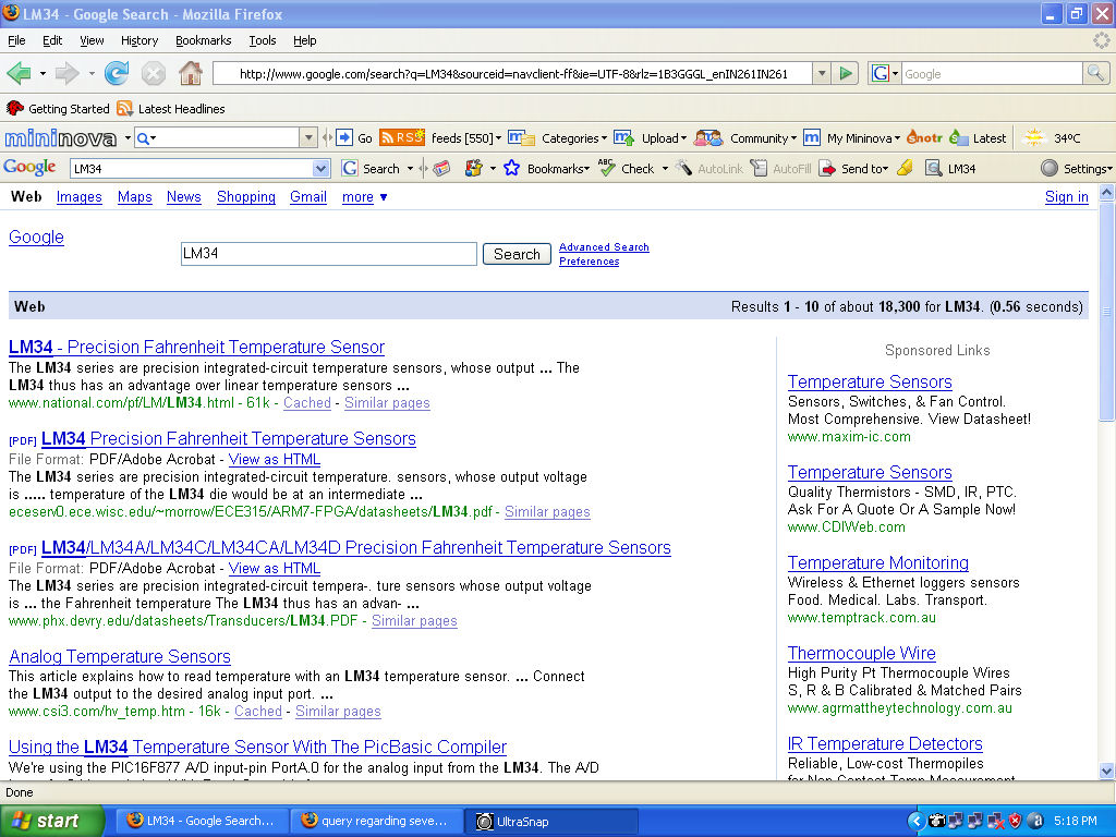
thanx for ur information on LM 35 sensors,could u provide me some more information about LM 34 sensor(fahrenheit sensor) ,its pin configuration and characteristics.
thanx for ur information on LM 35 sensors,could u provide me some more information about LM 34 sensor(fahrenheit sensor) ,its pin configuration and characteristics.
Fri Jun 20 2008, 05:24 pm
hello priya 123,
use this forum for help when your preliminary search doesn't give you good results.
before posting your queries try googling, don't expect spoon feeding here. below are the results for what you asked
![]()
next time such queries will be deleted without explanation.
Arun
use this forum for help when your preliminary search doesn't give you good results.
before posting your queries try googling, don't expect spoon feeding here. below are the results for what you asked
next time such queries will be deleted without explanation.
Arun
Powered by e107 Forum System

Robertrip
Fri Apr 26 2024, 11:20 am

ArnoldDiant
Fri Apr 26 2024, 03:53 am

RodneyKnorb
Thu Apr 25 2024, 07:08 pm

Williamjef
Thu Apr 25 2024, 02:08 pm

SamuelSmise
Thu Apr 25 2024, 09:56 am

DustinErele
Thu Apr 25 2024, 08:44 am

ztaletpzca
Wed Apr 24 2024, 11:19 pm

IrardlPex
Wed Apr 24 2024, 08:42 pm