News PIC projects
- coolmirza143
- Tue Jun 14 2011, 05:24 pm
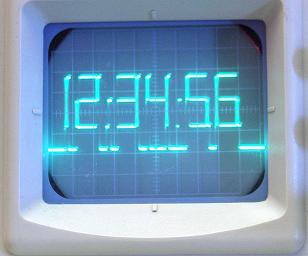
PIC Oscilloscope Clock
For those are not into electronics, you must know that an oscilloscope has basically only one timebase to move the spot horizontally from left to right with the same intensity. The vertical deviation is function to the input voltage. You understand immediately that you can't directly display 7 segment digits, because you can't move the spot from right to left.
![]()
By using X/Y mode, where the spot is controlled on two axes by two different voltages, it is possible to draw a picture (as in the examples mentioned above), but a fast digital to analog converter with two channels and at least 8 bits of resolution would be needed.
So we have to deal with a spot that always goes from left to right in the same period of time.
If we want to have a 7segment-like display, we have to draw :
vertical segments : easy to do, just change voltage up and down quickly a few times.
horizontal segments : easy to do, just set a voltage level and keep it as long as you need.
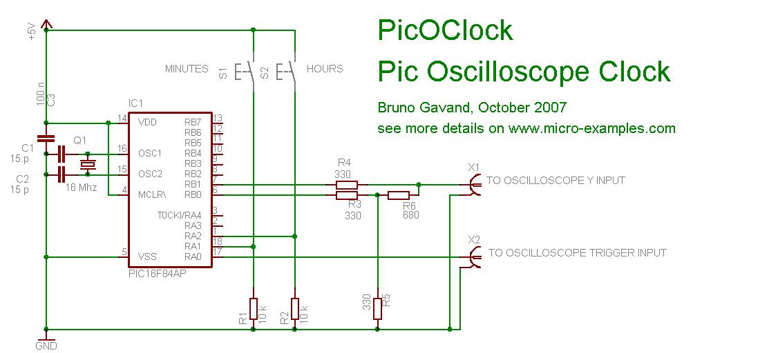
By using 2 PIC outputs and a basic R2R digital to analog converter, we can have up to four different voltage levels : 3 for the vertical segment, and another one where to put the spot when it is not in use to draw a segment.
But the problem is that a 7 segment digit may have up to 3 horizontal lines at a time (like 2, 3, 8, 9..) but we can draw only one during one spot deviation.
So we will have to cheat with retinal persistence and use multiple frames : since we can have only one vertical segment per period, three periods will be needed to draw a full 7 segment digit.
Supposing we want to display 12:34:56 on the screen :
During the first period, we will draw all vertical segments, and horizontal upper segments only :
As a game, I let you try to find out the spot trajectory.
Don't forget the rules :
you can't go backward
you can't clear the spot
But you can move so fast vertically that the eye can't see the spot moving.
The lowest line under the digits is not significant, it his the place where the spot is parked when not used to draw a segment.
Schematic Diagram:
![]()
Working Video
for more details see this LINK
For those are not into electronics, you must know that an oscilloscope has basically only one timebase to move the spot horizontally from left to right with the same intensity. The vertical deviation is function to the input voltage. You understand immediately that you can't directly display 7 segment digits, because you can't move the spot from right to left.
By using X/Y mode, where the spot is controlled on two axes by two different voltages, it is possible to draw a picture (as in the examples mentioned above), but a fast digital to analog converter with two channels and at least 8 bits of resolution would be needed.
So we have to deal with a spot that always goes from left to right in the same period of time.
If we want to have a 7segment-like display, we have to draw :
vertical segments : easy to do, just change voltage up and down quickly a few times.
horizontal segments : easy to do, just set a voltage level and keep it as long as you need.
By using 2 PIC outputs and a basic R2R digital to analog converter, we can have up to four different voltage levels : 3 for the vertical segment, and another one where to put the spot when it is not in use to draw a segment.
But the problem is that a 7 segment digit may have up to 3 horizontal lines at a time (like 2, 3, 8, 9..) but we can draw only one during one spot deviation.
So we will have to cheat with retinal persistence and use multiple frames : since we can have only one vertical segment per period, three periods will be needed to draw a full 7 segment digit.
Supposing we want to display 12:34:56 on the screen :
During the first period, we will draw all vertical segments, and horizontal upper segments only :
As a game, I let you try to find out the spot trajectory.
Don't forget the rules :
you can't go backward
you can't clear the spot
But you can move so fast vertically that the eye can't see the spot moving.
The lowest line under the digits is not significant, it his the place where the spot is parked when not used to draw a segment.
Schematic Diagram:
Working Video
for more details see this LINK


carpinteyrowrl
Fri Apr 19 2024, 02:51 pm

DonaldJAX
Fri Apr 19 2024, 01:08 pm

Lewisuhakeply
Thu Apr 18 2024, 06:00 pm

Darrellciz
Thu Apr 18 2024, 11:07 am

Charlessber
Thu Apr 18 2024, 09:29 am

BartonSem
Thu Apr 18 2024, 04:56 am

DonaldKnown
Thu Apr 18 2024, 12:24 am

utaletxcyw
Wed Apr 17 2024, 10:21 am