►Addressing modes
RAM memory locations can be accessed directly or indirectly.
1. Direct Addressing
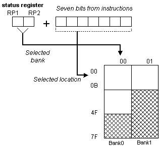
Direct Addressing is done through a 9-bit address. This address is obtained by connecting 7th bit of direct address of an instruction with two bits (RP1, RP0) from STATUS register as is shown on the following picture. Any access to SFR registers is an example of direct addressing.
Bsf     STATUS, RP0 ;Bankl
movlw   0xFF        ;w=0xFF
movwf   TRISA       ;address of TRISA register is taken from
                    ;instruction movwf
2. Indirect Addressing
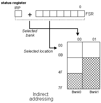
Indirect unlike direct addressing does not take an address from an instruction but derives it from IRP bit of STATUS and FSR registers. Addressed location is accessed via INDF register which in fact holds the address indicated by a FSR. In other words, any instruction which uses INDF as its register in reality accesses data indicated by a FSR register. Let's say, for instance, that one general purpose register (GPR) at address 0Fh contains a value of 20. By writing a value of 0Fh in FSR register we will get a register indicator at address 0Fh, and by reading from INDF register, we will get a value of 20, which means that we have read from the first register its value without accessing it directly (but via FSR and INDF). It appears that this type of addressing does not have any advantages over direct addressing, but certain needs do exist during programming which can be solved smoothly only through indirect addressing.

Such examples include sending a set of data via serial communication, working with buffers and indicators (which will be discussed further in a chapter with examples), or erasing a part of RAM memory (16 locations) as in the following instance.

Reading data from INDF register when the contents of FSR register is equal to zero returns the value of zero, and writing to it results in NOP operation (no operation).
Reading from EEPROM Memory
Setting the RD bit initializes transfer of data from address found in EEADR register to EEDATA register. As in reading data we don't need so much time as in writing, data taken over from EEDATA register can already be used further in the next instruction.
Sample of the part of a program which reads data in EEPROM, could look something like the following:

After the last program instruction, contents from an EEPROM address zero can be found in working register w.
Writing to EEPROM Memory
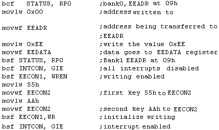
In order to write data to EEPROM location, programmer must first write address to EEADR register and data to EEDATA register. Only then is it useful to set WR bit which sets the whole action in motion. WR bit will be reset, and EEIF bit set following a writing what may be used in processing interrupts. Values 55h and AAh are the first and the second key whose disallow for accidental writing to EEPROM to occur. These two values are written to EECON2 which serves only that purpose, to receive these two values and thus prevent any accidental writing to EEPROM memory. Program lines marked as 1, 2, 3, and 4 must be executed in that order in even time intervals. Therefore, it is very important to turn off interrupts which could change the timing needed for executing instructions. After writing, interrupts can be enabled again.
Example of the part of a program which writes data 0xEE to first location in EEPROM memory could look something like the following:

NOTE: It is recommended that WREN be turned off the whole time except when writing data to EEPROM, so that possibility of accidental writing would be minimal. All writing to EEPROM will automatically clear a location prior to writing a new.