IO PORT PROGRAMING CHALANGE


I have answer to that too

Competitions will go like this..
1. Problem will be post on forum and entries will be accepted till a fixed date
2. After entries are received, A new thread will be created
3. all entries will be displayed and we will have voting on the basis of logic/code efficiency
4. After voting date is over. We will have our winner
>> We have to promise ourself to vote for the best


i.e. will there be individual probems posted for each forum heading?.
anyways, looks very promising and attractive. :-)


hello caze,
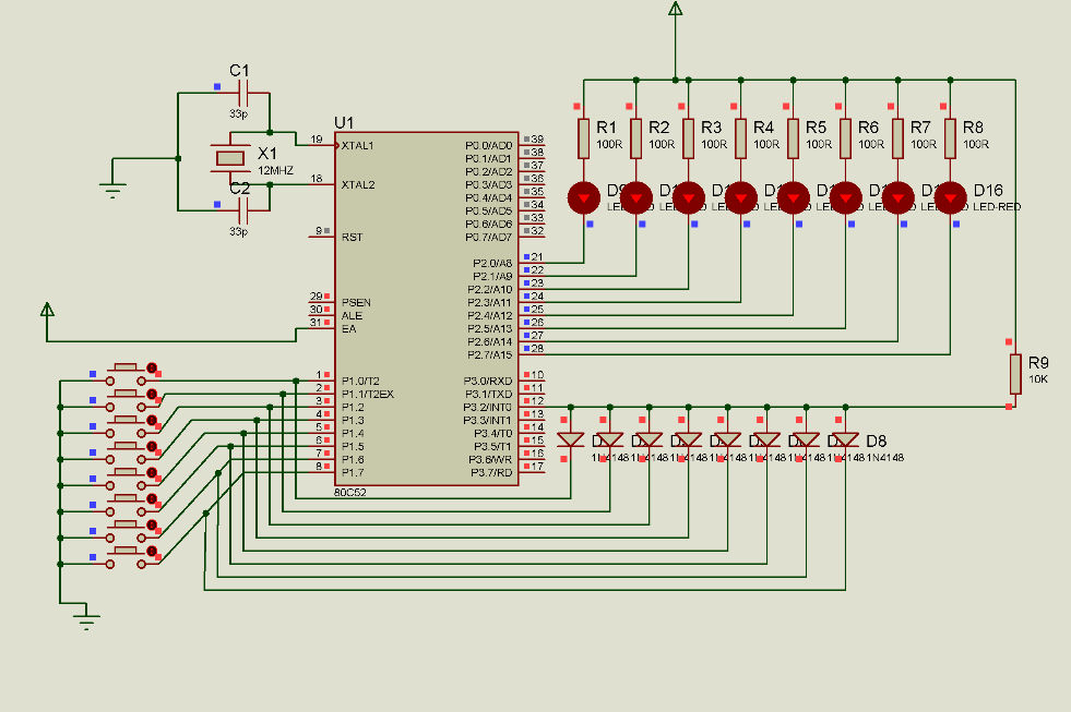
as promised here's my code and schematic, i have written for 8 I/Os your task is to further increase it to 10 I/Os (its easy after you go thru the code) - Enjoy !
: code deleted by Arun
i have simulated and tested the code using Ds89C430 and it works well !
ArunArun Kumar V

stated at the above of the diagram, u've posted code, but where is it? could u repost it, once again...so, it could be my reference for my assignment, i hope u'll consider my request...
as u can see, arun has posted the most important part of ur assignment which is the principle of operation and hardware which is more than half of ur assignment done. i would assume that writing the code for the above hardware should be quite simple for u if u have really understood the principle explained in the previous posts of this thread.
I am in perfect acceptance of aruns decision to delete the code as the same assignment seems to have been given to most of the members of this forum from ur place and it would be unfair (especially to ur faculty who gave u people this assignment) if most of ur collegues just download the code and complete the assignment without really understanding the concept( which is why u were given the assignemnt in the first place, right?).
So i would advice u on starting on something and then we can always suggest/comment on it.
good luck :-)


i need 30 seconds delay which is 600D but the max is 255D
so how do i get 30 secs? by setting tick time higher than 50msec? Biggest is 60+msec?
but still cannot get a total of 30seconds.
pls teach me how to get 30 secs...
Edit: Just think of an idea of making 2 loops, but the exact coding still not sure about it...
[ Edited Fri Sep 05 2008, 04:19 am ]
hello caze,
as promised here's my code and schematic, i have written for 8 I/Os your task is to further increase it to 10 I/Os (its easy after you go thru the code) - Enjoy !
: code deleted by Arun
i have simulated and tested the code using Ds89C430 and it works well !
ArunArun Kumar V
another noob question here, hope u all dun mind...
by comparing Arun's schematic n Junied's schematic (http://rapidshare.de/files/40330614/imp_scheme.pdf.html)
Arun's connect those buttons to P3.2(INT0) which Junied did not.
I know it is for interrupt purpose, but i not really clear about tis part.
Is it we must use interrupts to implemented tis functions? Is there any others way?
For example, below is a sample code i search thru the internet, it can poll between 2 inputs and countdown 10 secs but it does not uses interrupts. Is tis code correct?
(If you pressed switch A, and your program goes into a delay loop to give you the 10 sec delay, then switch B will not be polled, and therefore has no effect while the system is waiting for this 10 sec delay to complete.
The program below should give you some idea. It is not debugged, but the idea is there.
The two switches have to be polled regularly. Let the timer runs freely and overflow every 50 ms. If switch A is pressed, initialise the value of R1 to 200. Decrement R1 everytime the timer overflow. After 200 overflow (200 x 50ms = 10 s), R1 becomes zero, and the program turn off LED A. LED B is separately controlled by the value in R2.
MOV TMOD,#10H ; CONFIGURE TIMER 1
MOV TH1,#3CH ; ASSUME 12 MHZ CRYSTAL
MOV TL1,#B0H ; TIMER TAKES 50MS TO OVERFLOW
SETB TR1 ; START TIMER 1
POLL: ; POLL FOR THE SWITCHES
JNB P1.0,AA1 ; JUMP IF SWITCH A IS PRESSED
JNB P1.1,BB1 ; JUMP IF SWITCH B IS PRESSED
POLL2:
JNB TF1,POLL ; TIMER NOT OVERFLOW YET, CONTINUE TO POLL
CLR TF1
MOV TH1,#3CH
MOV TL1,#B0H
CJNE R1,#0,CNTDOWN_A
SETB P3.0 ; OFF LED A
CJNE R2,#0,CNTDOWN_B
SETB P3.1 ; OFF LED B
SJMP POLL
AA1:
MOV R1,#200D ; START TIMING
CLR P3.0 ; ON LED A
SJMP POLL2
BB1:
MOV R2,#200D
CLR P3.1 ; ON LED B
SJMP POLL2
CNTDOWN_A:
DEC R1
SJMP POLL
CNTDOWN_B:
DEC R2
SJMP POLL
)
well u thought of it right. but to generate a 30seconds tick (that is a very long time ), u may have to change the timer mode to 16 bits ( two bytes) and further add a two byte counter in the overflow interrupt. 30 seconds = 30,000,000 uS. == total 4 byte counter.pdi33
I do not understand "and further add a two byte counter in the overflow interrupt. 30 seconds = 30,000,000 uS. == total 4 byte counter."
Wat u mean by overflow interrupt? add 2 byte counter?
By setting timer mode to 16bits(TMOD,#10H) blah blah blah i get 50mS each cycle.
den i MOV R1,#200 to get 10secs. I cant MOV R1,#600 to get 30secs becoz the max is 255 only.
Can i do like tis? Like creating delay for multiplexing?
LOOP1: MOV R1,#200
LOOP2: MOV R2,#3 ;200*3=600 =)
LOOP3: DJNZ R1,$
DJNZ R2,LOOP2
p/s: becoz on the other thread Arun said tis "3) once Key is detected, particular LED is Lit and timer1 is loaded for 30sec delay
( 50mS X 20d = 1000mS or 1 Sec, for 30 sec increment a Register 30 times) after the delay the led is switched off."
how to do tis part?
already confuse between timer n counter, somore declare counters in timer0 ISR.
totally blur...

i feel you are trying to do too many things at the same time, pl. follow a step by step approach.
the solution i offered here is for this particular Challenge, so the connecting of Int0 pin with other input port pins works in this context and you don't have to connect it this way always in your other circuits.
now about the timer delay.
You have to use timer ISR ( interrupt Service Rotuine). in Data seg ( i,e RAM) define variables by some name like count_1......count_10 and also 10 flags by name like Flag_1.....Flag_10 and now read the algorithm carefully (point no.5):
5) in the timer0 ISR declare 10 counters (use registers/variables) check which flag/s is high( already set high in the Ex int.ISR), if a match is found increment that particular counter/s and reti continue till you reach 200 decimal ( 50mSec X 200 times = 10secs) once the counters reach 200 then stop the device and clear the flag/s
and now for 30 sec delay question.
first make a delay for 1 Sec and then use this 1 sec delay as basic tick to get multiple seconds/mins/hrs/days delay, here's a code snippet :
MAIN:
MOV TMOD,#01H  ; TIMER 0 MODE 1
MOV  TL0,#0B0H	 ;Lower Byte   ; 50 mS DELAY VALUES ( 12 Mhz XTAL)
MOV  TH0,#03CH	;Upper Byte
MOV R1,#20D       ; COUNTER FOR 1 SEC
MOV R2,#30D       ; COUNTER FOR 30 SECS
SET   TR0		;Run timer

CLR LED        ; LED IS ON
SJMP $


;TIMER0 ISR

CLR TR0
DJNZ R1,CONTINUE
MOV R1,#20D   ; RELOAD COUNTERS FOR NEXT CYCLE
DJNZ R2,CONTINUE
SETB  LED          ; AFTER COMPLETION OF  30 SEC DELAY OFF THE LED
MOV R2,#30D   ; RELOAD COUNTERS FOR NEXT CYCLE

CONTINUE:
MOV  TL0,#0B0H	 ;Lower Byte   ; 50 mS DELAY VALUES ( 12 Mhz XTAL)
MOV  TH0,#03CH	;Upper Byte
SETB TR0

RETI
Arun
[ Edited Sat Sep 06 2008, 12:51 am ]


