Heart Beat sensor


Tue Feb 15 2011, 10:50 pm
can anyone tell me the circuit and component of this circuit shown in image below....
http://www.sunrom.com/sensors/heart-beat-sensor
please....i need it as early as possible
thanks....
http://www.sunrom.com/sensors/heart-beat-sensor
please....i need it as early as possible
thanks....


Wed Feb 16 2011, 01:58 am
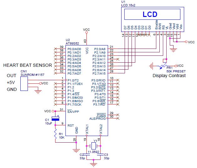
Let’s use this heart beat sensor and build a digital heart beat monitor. When a finger is put in the
sensor, it displays the beats per minute (BPM) rate.
![]()
The pulse signal is applied to the P1.0 input of U2 that is AT89S52 (Can be any 8051 type) which is
monitored by the program whenever this input goes high. Internally to U2, there is a counter which
counts how many 1ms intervals there are between two high going heart beat pulses. This number is
then divided by 60,000 and the result is the pulse rate. For example, if the pulse rate is 60 BPM
(beats per minute) there will be a pulse every second.
The duration of one heart beat
will be one seconds or 1000 x 1ms. Dividing 60,000 by 1000 will give the correct result of 60 which is shown on the display. If there is invalid result (BPM>200) it is invalid and waits for next cycle.
for more info see its data sheet all this is given in it..... read it carefully...
sensor, it displays the beats per minute (BPM) rate.
The pulse signal is applied to the P1.0 input of U2 that is AT89S52 (Can be any 8051 type) which is
monitored by the program whenever this input goes high. Internally to U2, there is a counter which
counts how many 1ms intervals there are between two high going heart beat pulses. This number is
then divided by 60,000 and the result is the pulse rate. For example, if the pulse rate is 60 BPM
(beats per minute) there will be a pulse every second.
The duration of one heart beat
will be one seconds or 1000 x 1ms. Dividing 60,000 by 1000 will give the correct result of 60 which is shown on the display. If there is invalid result (BPM>200) it is invalid and waits for next cycle.
// -=-=-=-=-=-=-=-=-=-=-=-=-=-=-=-=-=-=-=-=-=
// -=-=-=-=- Hardware Defines -=-=-=-=-=-=-=
// -=-=-=-=-=-=-=-=-=-=-=-=-=-=-=-=-=-=-=-=-=
sbit SENSOR = P1^0; //sensor is connected to this pin
unsigned int beatms;
float bpm;
char buf[20];
// -=-=-=-=-=-=-=-=-=-=-=-=-=-=-=-=-=-=-=-=-=
// -=-=-=-=- Main Program -=-=-=-=-=-=-=
// -=-=-=-=-=-=-=-=-=-=-=-=-=-=-=-=-=-=-=-=-=
void main()
{
// -=-=- Intialize variables -=-=-=
lcdInit();
// -=-=- Welcome LCD Message -=-=-=
lcdClear();
lcdGotoXY(0,0); // 1st Line of LCD
// "xxxxxxxxxxxxxxxx"
lcdPrint("DIGITAL HEART");
lcdGotoXY(0,1); // 2nd Line of LCD
// "xxxxxxxxxxxxxxxx"
lcdPrint("BEAT MONITOR");
beatms=0; // will store duration between two pulses
// -=-=- Program Loop -=-=-=
while(1)
{
while(SENSOR==0);// wait for high pulse from sensor
DelayNmS(10); // 10ms delay so that it does not listen to any noise
beatms = 10; // start counting beatms from 10ms since we have delay after pulse
while(SENSOR==1)// wait until signal is high
{
DelayNmS(1); //wait 1msec
beatms++; //keep incrementing counter each 1ms
}
while(SENSOR==0) //keep looping till signal goes back high, wait for next
{
DelayNmS(1); //wait 1msec
beatms++; //keep incrementing counter each 1ms
}
// beatms variable will now have time in ms between two high edge pulse
lcdClear();
lcdGotoXY(0,0);
lcdPrint("HEART RATE : ");
bpm = (float)60000/beatms; // see document of #1157 for this calculation
if(bpm >
 200)
{
lcdGotoXY(0,1);
sprintf (buf, "Processing......"); // Invalid, Wait for next cycle
lcdPrint(buf);
} else {
lcdGotoXY(0,1);
sprintf (buf, "%0.0f BPM", bpm); // Display reading in BPM
lcdPrint(buf);
}
}
}
for more info see its data sheet all this is given in it..... read it carefully...
AMINOR like this.
Wed Feb 16 2011, 08:32 pm
Thanks for that....
i hv already read the datasheet and not having problem of interfacing (actually not yet interfaced it)
but i m having problem with the sensor....
i dnt knw the circuit and component in it....
i hv already read the datasheet and not having problem of interfacing (actually not yet interfaced it)
but i m having problem with the sensor....
i dnt knw the circuit and component in it....


Wed Feb 16 2011, 11:14 pm
it uses simple light detector can be photo transistor with bright light
one circuit is on this link
http://www.8051projects.info/circuit.asp?im=monitor&desc=BIOMEDICAL-MONITORING-SYSTEM-%28AT89C2051-+-TX/RX%29
one circuit is on this link
http://www.8051projects.info/circuit.asp?im=monitor&desc=BIOMEDICAL-MONITORING-SYSTEM-%28AT89C2051-+-TX/RX%29
AMINOR like this.
Wed Feb 16 2011, 11:32 pm
simply connect an LCD and this sensor with micro controller and interface it,,,,,,it will give you exact heart beat no circuit needed.....
first test this sensor....then move forward...
you can add temperature sensor to it and can hear beat by using a speaker and also can use gsm modem with it and can interface it to make a remote patient monitoring system.....
as majoka gave you a link in above post it has some extra features like temperature sensor and also have wireless interface that is AM transmitter you can use GSM as one of my friends did this using GSM....
Sun Apr 17 2011, 12:01 am
sorry replying so late ....
working same ckt but still not getting results....
so plz tell me in the given ckt what the role of 470nF capacitor....??
and plz tell me what are the waveforms at
1. Across LDR
2. At pin 3
3. At pin 1
4. At pin 7
Thanks....
working same ckt but still not getting results....
so plz tell me in the given ckt what the role of 470nF capacitor....??
and plz tell me what are the waveforms at
1. Across LDR
2. At pin 3
3. At pin 1
4. At pin 7
Thanks....


Sun Apr 17 2011, 08:00 am
the 470nF along with the 47k resistor forms a high pass filter with a 7Hz corner frequency....basically a dc blocker.
Use some kind of a closed enclosure for the LED-LDR setup to minimise ambient disturbances.
The R16 preset is for setting the amplitude of the captured waveform.
The R17 is for setting the trigger level.
Initially keep R16 centered and without putting a finger make sure that there's no pulse generated at pin 7.
Now put the test finger and adjust R17 to get stable pulses at pin 7.
AMINOR like this.
Mon Apr 18 2011, 05:06 am
Thanks....
but heart beats are 72(normal) per minute i.e. 72/60 = 1.2 Hz
and the filter is 7 Hz high pass then how it will give the output....
plz tell me in details, im pretty poor in this ....
but heart beats are 72(normal) per minute i.e. 72/60 = 1.2 Hz
and the filter is 7 Hz high pass then how it will give the output....
plz tell me in details, im pretty poor in this ....
Mon Apr 18 2011, 06:46 pm
well a 1st order filter attenuates at 6dB/octave so it will still let in some useful signal to pass through,although attenuated.This is made-up with the gain provided by the opamp it seems.
Try adding another 470nF in parallel.
Are you getting any pulses at all at pin 7?
Try adding another 470nF in parallel.
Are you getting any pulses at all at pin 7?
Wed Apr 20 2011, 04:51 am
no i m not getting any pulses at pin 7....(without adding another 470 nF in parallel)
Powered by e107 Forum System

Lewisuhakeply
Thu Apr 18 2024, 06:00 pm

Darrellciz
Thu Apr 18 2024, 11:07 am

Charlessber
Thu Apr 18 2024, 09:29 am

BartonSem
Thu Apr 18 2024, 04:56 am

DonaldKnown
Thu Apr 18 2024, 12:24 am

utaletxcyw
Wed Apr 17 2024, 10:21 am

Anthonyvab
Wed Apr 17 2024, 08:48 am

RobertCix
Wed Apr 17 2024, 06:46 am