GSM modem interfacing to AT89C51


I need assembly program for the same..
I have prepared my own but it is not working:
here it is:
ORG 0000H
        MOV TMOD,#20H               //TIMER 1, MODE 2
        MOV TH1,#-3                //9600 BAUD RATE
        MOV SCON,#50H            //8 BIT, 1 STOP, EN ENABLED
        SETB TR1

        MOV DPTR,#MSG1
        ACALL H1
        ACALL DELAY
        MOV DPTR,#MSG2
        ACALL H1
        ACALL DELAY
        MOV DPTR,#MSG3
        ACALL H1
        ACALL DELAY
        MOV DPTR,#MSG4
        ACALL H1
        ACALL DELAY
        MOV DPTR,#MSG5
        ACALL H1
        ACALL DELAY
STAY: SJAMP STAY
H1:      CLR A
        MOVC A,@A+DPTR
        JZ B1
        ACALL SEND
        INC DPTR
        SJMP H1
B1:
        RET
SEND:     MOV SBUF,A
H2:     JNB TI,H2
        CLR TI
        RET
DELAY:  MOV R3,#50H
HERE2:  MOV R4,#50H
HERE:    DJNZ R4,HERE
        DJNZ R3,HERE2
        RET


ORG 300H
MSG1: DB "AT",0DH
      DB 0H
MSG2: DB "AT+CMGF=1",0DH
      DB 0H
MSG3: DB "ATE=0",0DH
      DB 0H
MSG4: DB "AT+CMGS=",'"8149111111"',0DH
      DB 0H
MSG5: DB "TEXT",0X1A
      DB 0H

      END
connections:
GSM modem has following on-board connections:
MAX232----->> RS232 (Female connector)
pin 7 ---> Pin 2
pin 8 ---> Pin 3
So i have done following connections after this:
RS232 (Female connector) ---> RE232(PCB male connector ) ( This o did because it was difficult to take connections from on-board Female connetor)
I took out following pins from RS232 male connector and connected to microcontroller:
RS232(PCB male connector ) ---> AT89C51
Pin 2 --> Pin 11
Pin 3--> Pin 10
Pin 5 Grounded.
Rest AT89C51 connetions:
Crystal oscillator 12 Mhz.
EN (Pin 31) -VCC
Pin 40-- VCC
Pin 20-- Gnd
Are these connetions are correct??
why my program is not working ??
can any one tell me assembly program to interface the same?
[ Edited Mon Jan 21 2013, 05:55 am ]


MAX232----->> RS232 (Female connector)
pin 7 ---> Pin 2
pin 8 ---> Pin 3
these connections are ok
So i have done following connections after this:
RS232 (Female connector) --->> RS232(PCB male connector )
I took out following pins from RS232 male connector and connected to micro controller
you has done a mistake here
connections should be like
RS232 (Female connector) --->> RS232(PCB male connector ) --->> MAX232 (IC) --->> Microcontroller
now RS232(PCB male connector) connections to max232
Pin 2 --> Pin 14 (max232)
Pin 3 --> Pin 13 (max232)
Pin 5 Grounded.
now max232 connections to micro controller
Pin 11 --> Pin 11 (TX)
Pin 12 --> Pin 10 (RX)
Pin 5 Grounded.
Like in the attached schematic
when modem power up it is not ready to sens sms
it need some time to be ready
in code you are just sending sms commands
that will not be treated
do it in this way
				 ORG 0000H
MOV TMOD,#20H //TIMER 1, MODE 2
MOV TH1,#-3 //9600 BAUD RATE
MOV SCON,#50H //8 BIT, 1 STOP, EN ENABLED
SETB TR1
; BIG DELY
ACALL DELAY
ACALL DELAY
ACALL DELAY


MOV DPTR,#MSG1
ACALL H1
ACALL DELAY
MOV DPTR,#MSG2
ACALL H1
ACALL DELAY
MOV DPTR,#MSG3
ACALL H1
ACALL DELAY
MOV DPTR,#MSG4
ACALL H1
ACALL DELAY
MOV DPTR,#MSG5
ACALL H1
ACALL DELAY

STAY: SJMP STAY

H1:
CLR A
MOVC A,@A+DPTR
JZ B1
ACALL SEND
INC DPTR
SJMP H1
B1:
RET

SEND:
MOV SBUF,A
H2: JNB TI,H2
CLR TI
RET


DELAY:
MOV R2,#10H
HERE3:
MOV R3,#0ffH
HERE2:
MOV R4,#0ffH
HERE:
DJNZ R4,HERE
DJNZ R3,HERE2
DJNZ R2,HERE3
RET


ORG 300H
MSG1: DB "AT",0DH
DB 0H
MSG2: DB "AT+CMGF=1",0DH
DB 0H
MSG3: DB "ATE=0",0DH
DB 0H
MSG4: DB "AT+CMGS=",'"8149111111"',0DH
DB 0H
MSG5: DB "TEXT",0X1A
DB 0H

END


i guess there's somthing ,misunderstanding :| The MAX232 IC is already on the GSM board. and connections have been taken out of it and given to the RS232 female connector. It is difficult to take connections from FEMALE connector , i just connected a male connector to it and took connections out of it. I have attached my circuit diagram just have a look and let me know if it is still wrong.
Ok
thank you By the way, in program, is it necessary to take into account 'RESPONSES' from modem?
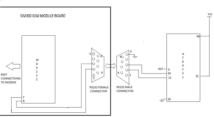
i guess there's somthing ,misunderstanding :| The MAX232 IC is already on the GSM board. and connections have been taken out of it and given to the RS232 female connector. It is difficult to take connections from FEMALE connector , i just connected a male connector to it and took connections out of it. I have attached my circuit diagram just have a look and let me know if it is still wrong.
MAX232 is line driver chip it convert 5 volt logic into RS232 logic level and vice versa
controller understand the logic of 1 and 0
1 = 5 volt
0 = 0 volt
RS232 standard is
1 = - 6 to 25 volt
0 = + 6 to 25 volt
now you are giving these signals directly to 8051 so 8051 is not able to understand it
now you need one more MAX232 ic that will convert it to 0 and 5 volt logic that 8051 can understand
hope so now you got it

By the way, in program, is it necessary to take into account 'RESPONSES' from modem?
it depend on the command that you are sending to modem
some time it is necessary to get response some time it is not
in my proteus design i did not use any MAX232 IC between Microcontroller and compim though it worked fine.. how?
i have attached my design.. just have a look...
in my proteus design i did not use any MAX232 IC between Microcontroller and compim though it worked fine.. how?
in Proteus there is no need of max232 but in real you must have to use max232


