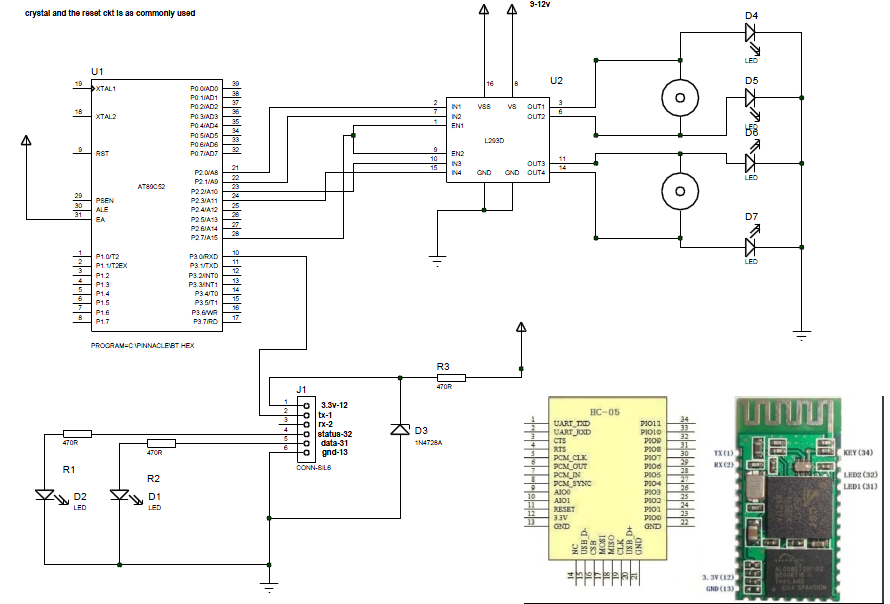
android contolled robot
Discussion in "Project Doubts" started by sjangra100 Mar 30, 2013.


Sat Mar 30 2013, 02:59 pm
hello sir
i have observed that there are a lot of extra components in the image of circuit than as shown on circuit diagram.
Now i am in confusion.....i need your help.
i want this project to be working for me.......for this i need the final list of electronics components required.
u are requested to mail me the list of components or comment here below.
my email id is- [email protected]


Sat Mar 30 2013, 04:21 pm
the project is not so complicated to make ....if u observe it fine...
just construct the ...basci ckt for microcontroller as done as usual......
if u buy a 5v compitable Bluetooth module the no need to use the zener or 3.3v regulator....
now....connect the BT serial pins to micro serial pins....
port2 o/p to moterdriver ckt ....use 4.7k pullup resister for port2...
for more info....see the data sheet for respective item
AT89S52...1
Bluetooth module......1
22pf cap....2
11mz crystal...1
4.7k resisters ....8
7805......1
LEDs....6
L293D...1
connectiing wires...
this all r required components...to start the project...
Sat Mar 30 2013, 04:33 pm
can u provide me the updated ckt diagrams for it....because the ckt diagram attacted with it does not show any capictors and 7805.
u can see the attachment of ckt diagram
u can see the attachment of ckt diagram
Sat Mar 30 2013, 04:36 pm
i have made the ckt keeping mind that any one would make this project may have the basic knowledge of microcontroller ckt..
and ..what exactly do u want ...
and ..what exactly do u want ...
Sat Mar 30 2013, 04:39 pm
can u locate the capictors and 7805 in this ckt diagram....in the attachment
Sat Mar 30 2013, 04:44 pm
there is no question of locating the 7805 and crystal and its cap as i have mention a sentence...n the reset ckt also..
here is the link for reference
![]()
here is the link for reference

Sat Mar 30 2013, 04:52 pm
i am beginer....i must clear u it.......if i just made connections acc. to ckt diagram in the attachment...ie without capacitors, crystal and 7805.....will the ckt work???
if no.....please provide me exact circuit.
if no.....please provide me exact circuit.
Sat Mar 30 2013, 04:56 pm
i am beginer....i must clear u it.......if i just made connections acc. to ckt diagram in the attachment...ie without capacitors, crystal and 7805.....will the ckt work???
if no.....please provide me exact circuit.sjangra100
in the 6th post i have attached a image ....for connections for crystal..7805..and capps
Sat Mar 30 2013, 05:08 pm
plzz u are requested to modify this circcuit diagram....i am unable to understand the above image
![]()


Sun Mar 31 2013, 03:27 am
i am beginer....i must clear u it.......if i just made connections acc. to ckt diagram in the attachment...ie without capacitors, crystal and 7805.....will the ckt work???sjangra100
No, it will not work.
Gaurav.k has left some components off his diagram to avoid clutter.
He has left off details of the power supply ,reset and the micro's crystal.
He has posted a circuit above, showing the extra connections needed.
Add these items to your circuit.
Use an 11.0592Mhz crystal, not the 12 Mhz shown.
On the 7805, add a 470 uF 25 volt capacitor between input and ground
and a 22 uF 16 volt capacitor between output(5 volts) and ground.
[ Edited Sun Mar 31 2013, 03:40 am ]
Powered by e107 Forum System

ArnoldDiant
Fri Apr 26 2024, 03:53 am

RodneyKnorb
Thu Apr 25 2024, 07:08 pm

Williamjef
Thu Apr 25 2024, 02:08 pm

SamuelSmise
Thu Apr 25 2024, 09:56 am

DustinErele
Thu Apr 25 2024, 08:44 am

ztaletpzca
Wed Apr 24 2024, 11:19 pm

IrardlPex
Wed Apr 24 2024, 08:42 pm

Charlestehed
Wed Apr 24 2024, 05:20 pm