Measure Voltage using Microcontroller


Tue Oct 15 2013, 02:00 am
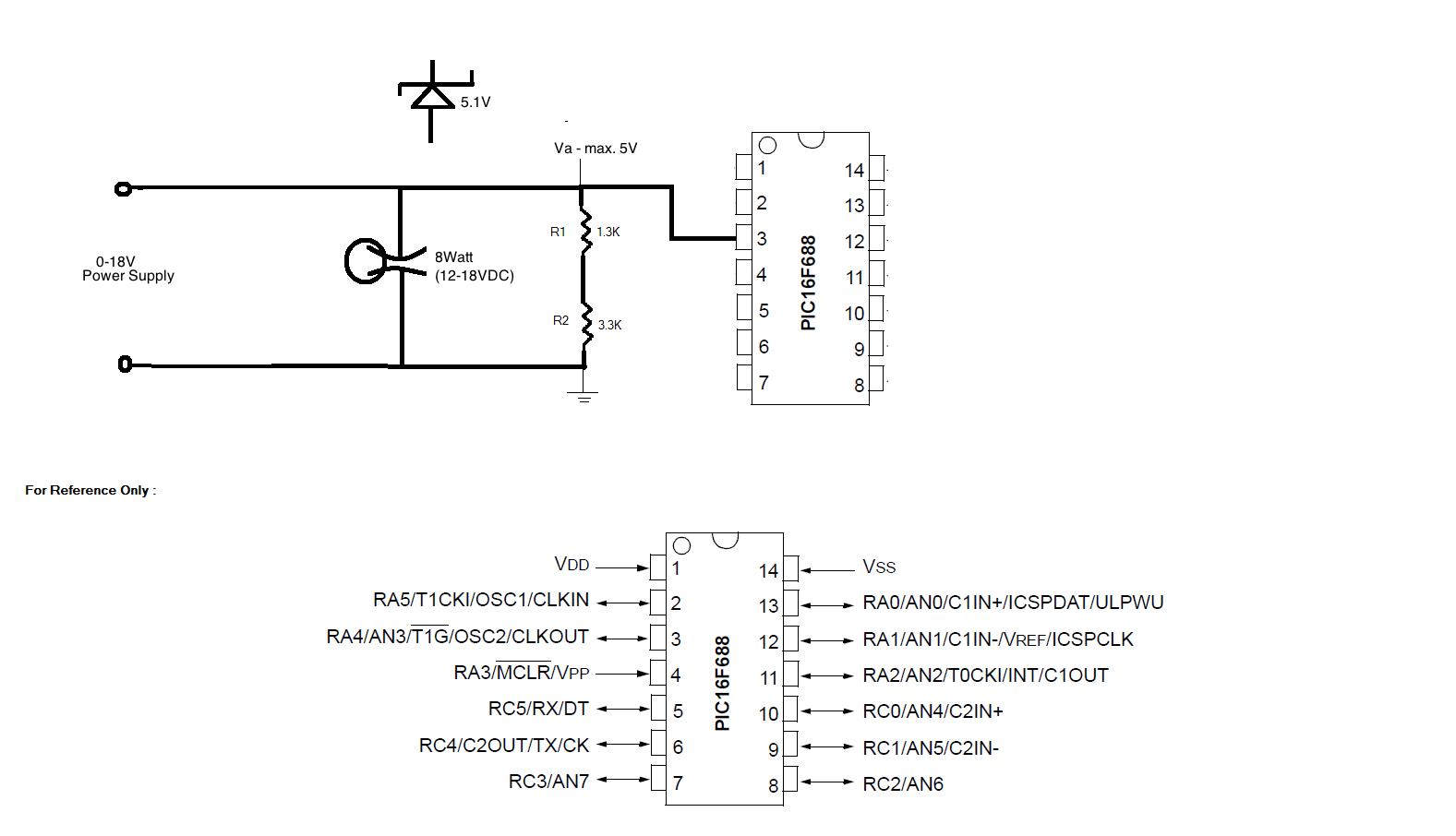
Ok, so I have done a lot of research on how to measure voltage using Microcontroller. I have read multiple articles and most of them talk about using resistor divider circuit to measure voltage. Now, say I want to measure voltage drop across a bulb rated at 12-18VDC and send this to ADC on the microcontroller. To do this I have designed the attached circuit. I was also planning on incorporate a 5.1V Zener Diode in my circuit to make sure that Va does not exceed 5V. Do you think I will run into errors using this circuit? Am I sending the right input to ADC? (I believe not!)
Any suggestions/help would be appreciated.
Thanks guys!
Any suggestions/help would be appreciated.
Thanks guys!
[ Edited Tue Oct 15 2013, 02:18 am ]


Tue Oct 15 2013, 12:54 pm
check this simple digital voltmeter project:
http://www.8051projects.net/download-d214-simple-digital-voltmeter-using-8051.html
In this project I have explained how to design proper voltage divider for your design or voltage range.
http://www.8051projects.net/download-d214-simple-digital-voltmeter-using-8051.html
In this project I have explained how to design proper voltage divider for your design or voltage range.
dikshac like this.
Tue Oct 15 2013, 07:04 pm
Thanks for you reply, Ajay.
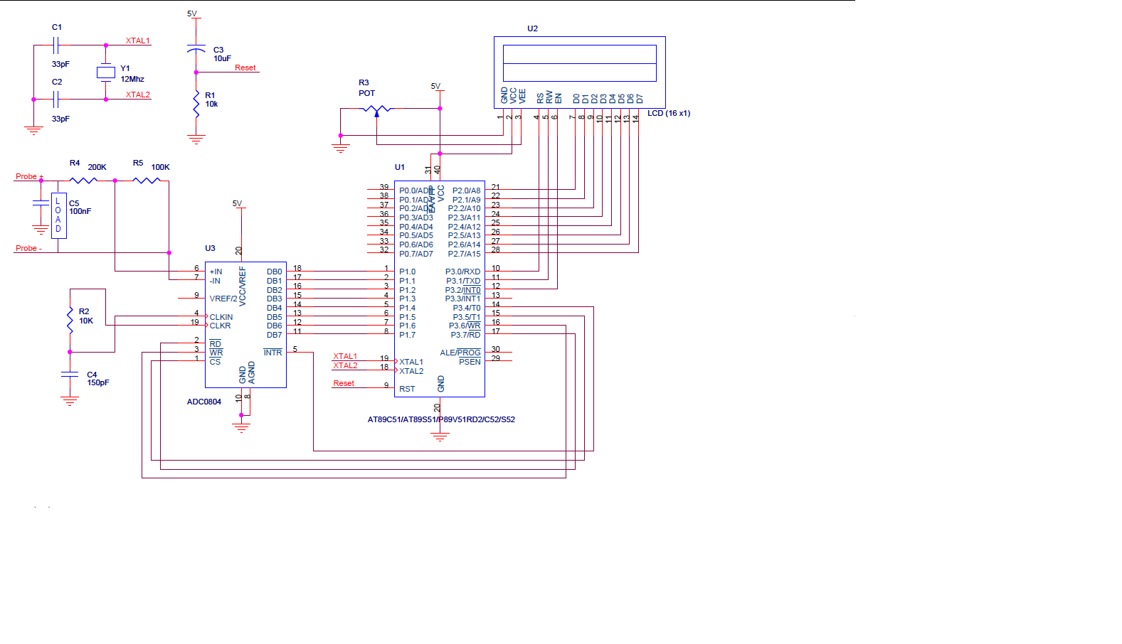
Can I connect my load, in this case, a 12-18VDC bulb between Probe+ and Probe-? Please see the attached file...
Would that give me the voltage drop at my load?
![]()
EDITED:
Sorry I just noticed that I moved the text for the capacitor next to the load. Please ignore that. The load is still a bulb. Also, I understand I'd have to play with resistances a little if my input is 18V. I believe all that would change,would bethe resistances in the voltage divider circuit... everything else would be pretty much the same, right? I have no clue how you go about finding the values of capacitors.
Thanks again, Ajay.
Can I connect my load, in this case, a 12-18VDC bulb between Probe+ and Probe-? Please see the attached file...
Would that give me the voltage drop at my load?
EDITED:
Sorry I just noticed that I moved the text for the capacitor next to the load. Please ignore that. The load is still a bulb. Also, I understand I'd have to play with resistances a little if my input is 18V. I believe all that would change,would bethe resistances in the voltage divider circuit... everything else would be pretty much the same, right? I have no clue how you go about finding the values of capacitors.
Thanks again, Ajay.
[ Edited Tue Oct 15 2013, 07:20 pm ]
Wed Oct 16 2013, 06:49 pm
Yeah, I saw that. I know how to find the values for resistors, but just wanted to confirm the probes were where you apply the input voltage. Also, I worked on Multisim simulation last night and I have all connections done right. Multisim doesn't have ADC0804, so I ended up using the Generic ADC which does not have CLK IN, CLK R pins. I was curious if that was necessary. This is pretty much what it has -
![]()

Fri Oct 18 2013, 02:46 am
Did you include the proteus simulation in the zip file? If yes, what would the extension be?
Fri Oct 18 2013, 01:26 pm
I dont remember if its included it or not. see if .dsn file is there or not. that would be proteus design file.
Fri Oct 18 2013, 06:59 pm
Nope, I don't see it, Ajay. Could you include that in the zip file if you still have it.
Thanks a lot.
PS: You've a great website here. I would love to share my project here, once I am done.
Thanks for all your help!
Thanks a lot.
PS: You've a great website here. I would love to share my project here, once I am done.
Thanks for all your help!
Powered by e107 Forum System

Richardgar
Sat Apr 20 2024, 11:05 am

AntoniaRoons
Fri Apr 19 2024, 09:59 pm

carpinteyrowrl
Fri Apr 19 2024, 02:51 pm

DonaldJAX
Fri Apr 19 2024, 01:08 pm

Lewisuhakeply
Thu Apr 18 2024, 06:00 pm

Darrellciz
Thu Apr 18 2024, 11:07 am

Charlessber
Thu Apr 18 2024, 09:29 am

BartonSem
Thu Apr 18 2024, 04:56 am