555 circuit doubt
Discussion in "Electronics" started by prajwalsnh Dec 23, 2013.


Mon Dec 23 2013, 12:39 pm
Hello friends,
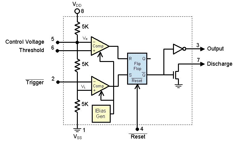
I have a doubt in internal circuit of 555 IC. In web there are two types of circuit which are making hard to undersatand the circuit operation. Im attaching the two pictures here. Please guide me which is the correct one.
![]()
![]()
In the above two circuit which is the correct one? In first circuit the trigger pin is NEGATIVE of OP-AMP where as in second circuit its POSITIVE of OP-AMP. Also the threshold pins are reversed. Which is the correct circuit to be followed. Help please
I have a doubt in internal circuit of 555 IC. In web there are two types of circuit which are making hard to undersatand the circuit operation. Im attaching the two pictures here. Please guide me which is the correct one.
In the above two circuit which is the correct one? In first circuit the trigger pin is NEGATIVE of OP-AMP where as in second circuit its POSITIVE of OP-AMP. Also the threshold pins are reversed. Which is the correct circuit to be followed. Help please
[ Edited Mon Dec 23 2013, 12:41 pm ]


Wed Dec 25 2013, 01:04 am
The first picture is correct.. If you ever need a clarification.. just follow datasheet 
Wed Dec 25 2013, 11:38 am
@Ajay Bhargav
Thank you sir I saw the datasheet but only the block diagram was given i wanted to know the internal circuit. so
Thank you sir
I saw the datasheet but only the block diagram was given i wanted to know the internal circuit. so Thu Dec 26 2013, 02:05 pm
Did you check page 3 of datasheet? it's Functional block diagram of 555 Timer.
Thu Dec 26 2013, 04:30 pm
@Ajay Bhargav
Sir im attaching the datasheet. In tat data sheet in first page there is a block diagram tats it. after that there is application notes.
Sir im attaching the datasheet. In tat data sheet in first page there is a block diagram tats it. after that there is application notes.
Powered by e107 Forum System

Richardedils
Wed Apr 24 2024, 04:07 am

ChrisLub
Tue Apr 23 2024, 05:21 pm

Davidbab
Tue Apr 23 2024, 10:41 am

Richardrit
Tue Apr 23 2024, 09:54 am

HenryLaf
Mon Apr 22 2024, 03:50 pm

bleradrar
Mon Apr 22 2024, 06:38 am

ppu-pro_ka
Sun Apr 21 2024, 07:39 pm

Infewow
Sun Apr 21 2024, 06:30 pm