PWM Deadtime Calculation for PWM


Fri Nov 21 2014, 08:01 pm
@ExperimeterUK
Forgot my last question.
As i told before that i have deadtime value as Input, from 0,5v to 3,25v. so from 2 to 24.
In which form i have to convert my deadtime inputed value?
when i write in Program deadtime(2). It takes easily but how can i give as Input. I alread convert this value into mV through ADC.
But i am bit confused how cani use this value to write deadtime?
When i run this program than PWM siognals jump irregularly.
Regards
Max
Forgot my last question.
As i told before that i have deadtime value as Input, from 0,5v to 3,25v. so from 2 to 24.
In which form i have to convert my deadtime inputed value?
when i write in Program deadtime(2). It takes easily but how can i give as Input. I alread convert this value into mV through ADC.
But i am bit confused how cani use this value to write deadtime?
while(1)
{
       if ( AtoDdoneflg )     // A/D got a new sample ?
       {
	if(AMux_Flag == 0) //Deadtime Channel selected
	{														Deadtime_Ans1 =  ADC_DelSig_CountsTo_mVolts( Deadtime_Ans );  						              if ( ( Deadtime_Ans1 >
 Deadtime_Ans_Old  + 10 ) || ( Deadtime_Ans1 < Deadtime_Ans_Old - 10 ) )
	            {
		Deadtime_Ans_Old = Deadtime_Ans1;

		// Enable PWM
		PWM_1_WritePeriod( (300 );
                                   PWM_1_WriteCompare1(141 );
		PWM_1_WriteCompare1(141);
		PWM_1_WriteDeadTime(Deadtime_Ans1 );
                            }
	}
	  AtoDdoneflg = 0;		// Reset A/D EOC flag
}
When i run this program than PWM siognals jump irregularly.
Regards
Max
[ Edited Fri Nov 21 2014, 08:14 pm ]


Sat Nov 22 2014, 11:45 am
@ExperimenterUK
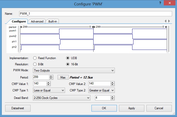
I make small table to observe Output with same period & compare value but changed Deadtime value.
Period = 300
Compare = 141
Deadtime-------ΔX------Duty
10------450ns--------43.5%
20------860ns--------40.2%
5--------250ns-------45.2%
2--------125ns-------46.2%
24--------1µs---------38.9%
i got ΔX right, which i needed so my clock is done (25MHz). But The Duty i Need always 47% What can i do for thisMax.otto
I'm not sure what you are asking.
With no dead time and maximum, equal phase lengths, each will be 50% of a cycle.
As you increase dead time the length of each phase will reduce,
that's what deadtime does.
I'm not sure PWM and the sort of phase length control you are doing
are the same thing.
while(1)
{
       if ( AtoDdoneflg )     // A/D got a new sample ?
       {
	if(AMux_Flag == 0) //Deadtime Channel selected
	{														Deadtime_Ans1 =  ADC_DelSig_CountsTo_mVolts( Deadtime_Ans );  						              if ( ( Deadtime_Ans1 >
 Deadtime_Ans_Old  + 10 ) || ( Deadtime_Ans1 < Deadtime_Ans_Old - 10 ) )
	            {
		Deadtime_Ans_Old = Deadtime_Ans1;

		// Enable PWM
		PWM_1_WritePeriod( (300 );
                                   PWM_1_WriteCompare1(141 );
		PWM_1_WriteCompare1(141);
		PWM_1_WriteDeadTime(Deadtime_Ans1 );
                            }
	}
	  AtoDdoneflg = 0;		// Reset A/D EOC flag
}
When i run this program than PWM siognals jump irregularly.
Regards
MaxMax.otto
I count four opening braces '{' and only three closing braces '}'
Where is the missing brace ?
[ Edited Sat Nov 22 2014, 11:48 am ]
Mon Nov 24 2014, 02:35 pm
@ExperimenterUK
Only 1 question. I wrote in program deadtime(2). This 2 i have to give as analog Input from range 2 to 24. [bHow can i give Deadtime as Input? ][/b]
Regards
Max
Only 1 question. I wrote in program deadtime(2). This 2 i have to give as analog Input from range 2 to 24. [bHow can i give Deadtime as Input? ][/b]
Regards
Max
Tue Nov 25 2014, 03:24 pm
Hello all,
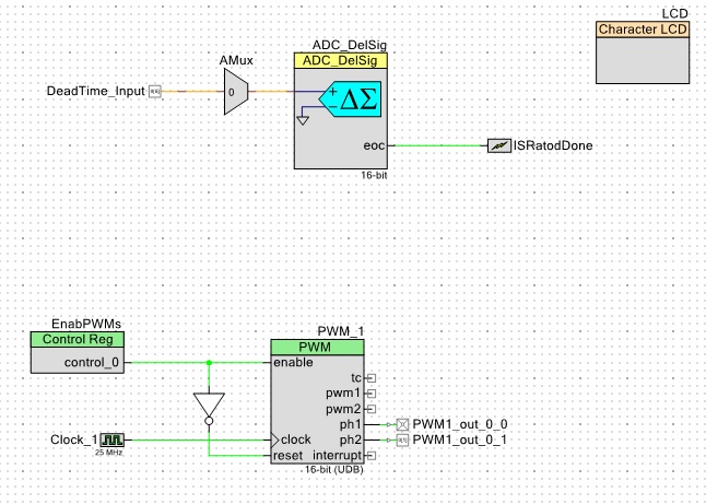
i was bit confused of my requirment. But now i m sure abt it. I want to give deadtime as Input with vary Duty cycle.
I am working with PSoC.
Deadtime Input value is for 0,5v = 205ns & 3,25v = 1μs. (like 205ns, 250ns, 290ns, 330ns....1μs = 40ns Step). .
pls check the attached files.
Regards
Max
![]()
![]()
![]()
![]()
i was bit confused of my requirment. But now i m sure abt it. I want to give deadtime as Input with vary Duty cycle.
I am working with PSoC.
Deadtime Input value is for 0,5v = 205ns & 3,25v = 1μs. (like 205ns, 250ns, 290ns, 330ns....1μs = 40ns Step). .
pls check the attached files.
Regards
Max


Powered by e107 Forum System

AntoniaRoons
Fri Apr 19 2024, 09:59 pm

carpinteyrowrl
Fri Apr 19 2024, 02:51 pm

DonaldJAX
Fri Apr 19 2024, 01:08 pm

Lewisuhakeply
Thu Apr 18 2024, 06:00 pm

Darrellciz
Thu Apr 18 2024, 11:07 am

Charlessber
Thu Apr 18 2024, 09:29 am

BartonSem
Thu Apr 18 2024, 04:56 am

DonaldKnown
Thu Apr 18 2024, 12:24 am