Need help on ULN2803 IC
Discussion in "Electronics" started by pnp May 8, 2008.


Thu May 08 2008, 07:15 am
1) I have a 12v 7-segment display. I need to drive this 7-segment using ULN2803 driver.
can some body tell me how can i do it.
2) Also i want to know how ULN2803 can be used to drive the relay circuit.
![]()
can some body tell me how can i do it.
2) Also i want to know how ULN2803 can be used to drive the relay circuit.


Thu May 08 2008, 04:43 pm
Hope you've got the common-anode type 7-seg.
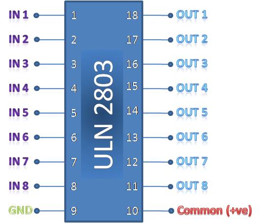
Just connect the individual segments to the ULN outputs.
eg a to out1,b to out2, c to out3 and so on.
On the other side connect the inputs(in1 to in8) to a uc port(hope you're using a microcontroller in the 1st place).
Now by writing a '1' to a port pin,the corresponding segment will light up.
For writing digits,send the fol. hex values to the port...
Digit........ Port value(in hex)
--------------------------------
0........... C0
1........... F9
2........... A4
3........... B0
4........... 99
5........... 92
6........... 82
7........... F8
8........... 80
9........... 98
As for the relay,simply connect one terminal of its coil to an 'out' pin and the other terminal to Vcc.Now when the corresponding input pin is driven high,the relay will come on.
pnp like this.


Fri May 09 2008, 02:50 am
Hi sashijoseph and abbas1707 ,
Thank you very much for your help.
It looks like this will solve my problem.
Thank you very much for your help.
It looks like this will solve my problem.

Fri Apr 17 2009, 09:20 am
i am connecting a buzzer and electromagnetic lock using the uln 2803 driver,can any one help me on the connection?
for 8051 microcontroller part,i am using port 2.7 and port 2.6.
can anyone help me on the program?because it don seem to work...
first i clear both port :
CLR P2.7
CLR P2.6
THEN once the person can access the door for eg the code would be:
SETB P2.7
SETB P2.6
CALL DELAY
THE assembly program are something like above,both my em lock and buzzer seem like not working.my buzzer keep on buzzing after turn on the power.please help


Sun Apr 19 2009, 06:34 pm
I have a problem with this IC.
I am trying to drive a stepper motor using 2803 and 2003 but I am not getting any output from the IC. I have given 12V between pin 10 and 9 and giving 6v to input side (pin 1-8) but I am getting only 0.6v at the output. Same case with ULN2003. what am I doing wrong?
I am trying to drive a stepper motor using 2803 and 2003 but I am not getting any output from the IC. I have given 12V between pin 10 and 9 and giving 6v to input side (pin 1-8) but I am getting only 0.6v at the output. Same case with ULN2003. what am I doing wrong?


Mon Apr 20 2009, 04:33 am
I have a problem with this IC.
giving 6v to input side (pin 1-8) but I am getting only 0.6v at theabhishek_h
This kind of chip sinks current, it can't source it.
0.6 volts at the output, when 'on' is correct.
[ Edited Mon Apr 20 2009, 04:36 am ]
Powered by e107 Forum System

ztaletpzca
Wed Apr 24 2024, 11:19 pm

IrardlPex
Wed Apr 24 2024, 08:42 pm

Charlestehed
Wed Apr 24 2024, 05:20 pm

Robertgurse
Wed Apr 24 2024, 02:43 pm

Richardedils
Wed Apr 24 2024, 04:07 am

Malcolmaccek
Wed Apr 24 2024, 01:21 am

ChrisLub
Tue Apr 23 2024, 05:21 pm

Davidbab
Tue Apr 23 2024, 10:41 am