Frequency Counter using AT89C2051 and LCD (Assembly)
Basic Level Skills: Not specified Wed Oct 28 2009, 02:36 am 

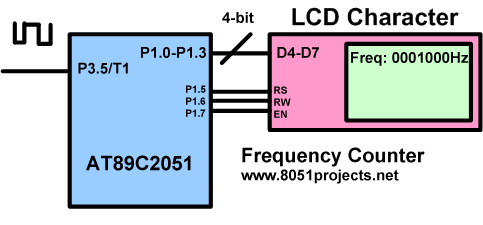
A very simple easy to make Frequency counter project. This project is powered with small AT89C2051 microcontroller with LCD. Block Diagram of circuit is shown below. It can support a wide range of frequency input starting from 1Hz to ~16.5Mhz, rest depends on pin characteristics.
Theory of Operation
As we all know frequency of a signal is number of cycle per second. I made use of this logic to calculate frequency of the input signal.
8051 has two timers, Timer 0 is configured for 1 second delay to sample the input signal and Timer 1 is used as a counter to calculate number of cycles in that 1 second. If timer1 overflows then the overflow is counter in another register which is considered as the high byte of Frequency. Input signal is provided at P3.5/T1 which is input for Timer 1 in counter mode. LCD is connected to microcontroller port 1 in 4-bit mode. Currently program is using 2 Line LCD but it can be used for 1 line LCD too.
Program initializes the Timer0 in 16-bit mode with 50mS delay value, a tick value of 20 is loaded to have total delay of 1s (50 x 20 = 1000 mS). Timer 1 is configured in 16-bit counter mode. After a sample of 1 sec, we get the number of cycles hence the frequency of input signal from timer1 registers (TH1:TL1) and high byte of Frequency. So total 3 byte value is then converted to a decimal equivalent represented in hex. This decimal value is then updated to LCD. The whole process repeats again.
Files:
1. FreqCounter.asm - Main program
2. FreqCounter.hex - Hex file
3. frequency_counter.png - Block Diagram
4. Schematic.pdf - circuit
For any doubts and suggestions please use forum
Use the Download button below to download this project.
Tags Frequency Counter using AT89C2051 and LCDFrequency Counter using 8051
- Author
- Ajay Bhargav
- Author email
- [email protected]
- Author website
- www.rickeyworld.info
Description

A very simple easy to make Frequency counter project. This project is powered with small AT89C2051 microcontroller with LCD. Block Diagram of circuit is shown below. It can support a wide range of frequency input starting from 1Hz to ~16.5Mhz, rest depends on pin characteristics.
Theory of Operation
As we all know frequency of a signal is number of cycle per second. I made use of this logic to calculate frequency of the input signal.
8051 has two timers, Timer 0 is configured for 1 second delay to sample the input signal and Timer 1 is used as a counter to calculate number of cycles in that 1 second. If timer1 overflows then the overflow is counter in another register which is considered as the high byte of Frequency. Input signal is provided at P3.5/T1 which is input for Timer 1 in counter mode. LCD is connected to microcontroller port 1 in 4-bit mode. Currently program is using 2 Line LCD but it can be used for 1 line LCD too.
Program initializes the Timer0 in 16-bit mode with 50mS delay value, a tick value of 20 is loaded to have total delay of 1s (50 x 20 = 1000 mS). Timer 1 is configured in 16-bit counter mode. After a sample of 1 sec, we get the number of cycles hence the frequency of input signal from timer1 registers (TH1:TL1) and high byte of Frequency. So total 3 byte value is then converted to a decimal equivalent represented in hex. This decimal value is then updated to LCD. The whole process repeats again.
Files:
1. FreqCounter.asm - Main program
2. FreqCounter.hex - Hex file
3. frequency_counter.png - Block Diagram
4. Schematic.pdf - circuit
For any doubts and suggestions please use forum
Use the Download button below to download this project.
Tags Frequency Counter using AT89C2051 and LCDFrequency Counter using 8051
Filesize
19.51 kB
Downloads
43660
Rating
- << Previous [Electronic Voting machine with Managed Control Unit (Project Report Included)]
- Back to list
- [C51 Snakes - A Nokia inspired game built on 8051] Next >>
Comments
sandeep kumar
15 Jul 2014: 12:25 pm
i need c code of this project kindly mail me on [email protected]
Ogu Reginald
12 May 2015: 03:14 am
This is a good project.
Please I need the c source code for the project.
Feel free to email me: [email protected]
If the c source code is not available, I want the frequency to be divided by 7 and the final answer displayed on the LCD.
Please I need the c source code for the project.
Feel free to email me: [email protected]
If the c source code is not available, I want the frequency to be divided by 7 and the final answer displayed on the LCD.
14 May 2015: 10:20 am
@ Ogu Reginald, You can understand the concept and implement the same on your own in C. Its really simple.
Chinh 299
13 Jun 2020: 18:48 pm
can you give the flowchart and detail comment of there code ?
Auden
23 Nov 2020: 14:13 pm
hi, Your Code is working but i have a problem while simulation on proteus i am giving input frequency from generator of 1000Hz but on output LCD its showing 1085HZ plz help.