News Item: Arduino Based Digital Compass
(Category: Arduino)
Posted by ajay_bhargav
Thu Mar 08 2012, 11:21 am
A simple digital compass can be made using cmp03 compass sensor interfacing Arduino and output can be displayed on 16*2 lcd. Thanks to Santosh Mishra for submitting this project and making a valuable contribution.
![]()
Parts Needed
arduino board ,16*2 lcd ,cmp03 compass sensor ,general purpose pcb,wires solder iron,comb connectors etc
Arduino Board
Arduino is an open-source electronics prototyping platform based on flexible, easy-to-use hardware and software. It's intended for artists, designers, hobbyists, and anyone interested in creating interactive objects or environments. you can make you own Arduino Board see the links below
Make Your Own Arduino
Pinguino, PIC Based Arduino Clone
Boarduino, Solderless Breadboard Arduino Clone
Compass Sensor(cmp03)
The compass uses the Philips KMZ51 magnetic field sensor, which is sensitive enough to detect the Earths magnetic field. The output from two of them mounted at right angles to each other is used to compute the direction of the horizontal component of the Earths magnetic
field.see data sheet for detail
LCD
a general type 16*2 lcd is used
Schematic Diagram and Explanation of it
Detailed Schematic coming soon in download section
The Arduino uses 7bit I2C addresses, and our own documentation uses 8bit addresses. For example our CMPS03 is at address 0xc0, but on the Arduino you will use 0x60. The Arduino address is the same as our address, but shifted right by 1 bit. The binary of 0xC0 is 11000000, the binary of 0x60 is 01100000.
The Arduino will shift this left by 1bit and add the Read/Write bit automatically. This uses the I2C bus to connect the Arduino to the CMPS03. It reads the bearing as a two byte integer and displays the bearing as a number 0-359 on 16*2 lcd .
connection of circuit diagram is easy scl(2) and sda(3) is pulled up using 4.7 kohm resiters and scl is connected to anolog in A5 pin of arduino and sda is connected to anologue in A4 of arduino.LCD
connections are 4,6 and 11,12,13,14 is connected to 12, 11 and 5,4,3,2 respectively ,5pin of lcd is grounded .A 330ohms resistor is connected to pin 15 vcc if you need back light other wise can be left open.
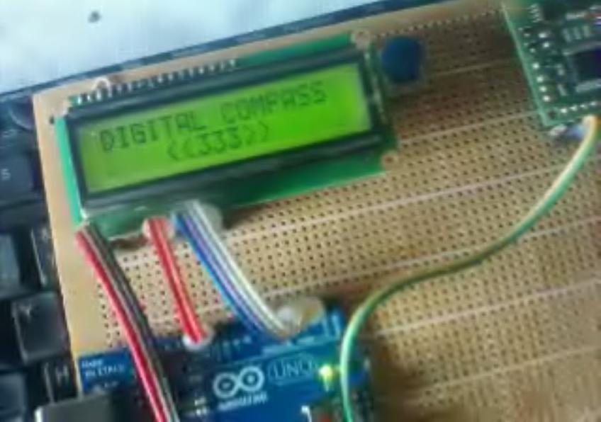
Digital Compass in Action
Hex and C file
Click Here to Download
This news item is from Rickey's World of Microcontrollers & Microprocessors
( http://www.8051projects.net/news.php?extend.184 )
(Category: Arduino)
Posted by ajay_bhargav
Thu Mar 08 2012, 11:21 am
A simple digital compass can be made using cmp03 compass sensor interfacing Arduino and output can be displayed on 16*2 lcd. Thanks to Santosh Mishra for submitting this project and making a valuable contribution.
Parts Needed
arduino board ,16*2 lcd ,cmp03 compass sensor ,general purpose pcb,wires solder iron,comb connectors etc
Arduino Board
Arduino is an open-source electronics prototyping platform based on flexible, easy-to-use hardware and software. It's intended for artists, designers, hobbyists, and anyone interested in creating interactive objects or environments. you can make you own Arduino Board see the links below
Make Your Own Arduino
Pinguino, PIC Based Arduino Clone
Boarduino, Solderless Breadboard Arduino Clone
Compass Sensor(cmp03)
The compass uses the Philips KMZ51 magnetic field sensor, which is sensitive enough to detect the Earths magnetic field. The output from two of them mounted at right angles to each other is used to compute the direction of the horizontal component of the Earths magnetic
field.see data sheet for detail
LCD
a general type 16*2 lcd is used
Schematic Diagram and Explanation of it
Detailed Schematic coming soon in download section
The Arduino uses 7bit I2C addresses, and our own documentation uses 8bit addresses. For example our CMPS03 is at address 0xc0, but on the Arduino you will use 0x60. The Arduino address is the same as our address, but shifted right by 1 bit. The binary of 0xC0 is 11000000, the binary of 0x60 is 01100000.
The Arduino will shift this left by 1bit and add the Read/Write bit automatically. This uses the I2C bus to connect the Arduino to the CMPS03. It reads the bearing as a two byte integer and displays the bearing as a number 0-359 on 16*2 lcd .
connection of circuit diagram is easy scl(2) and sda(3) is pulled up using 4.7 kohm resiters and scl is connected to anolog in A5 pin of arduino and sda is connected to anologue in A4 of arduino.LCD
connections are 4,6 and 11,12,13,14 is connected to 12, 11 and 5,4,3,2 respectively ,5pin of lcd is grounded .A 330ohms resistor is connected to pin 15 vcc if you need back light other wise can be left open.
Digital Compass in Action
Hex and C file
Click Here to Download
This news item is from Rickey's World of Microcontrollers & Microprocessors
( http://www.8051projects.net/news.php?extend.184 )