New age Car indicator system


Wed Mar 16 2011, 10:14 pm
Hello
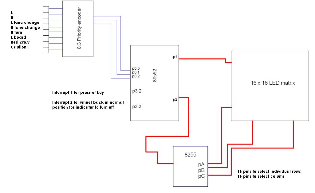
As my first uC based project, I am trying to make a 16 x 16 LED panel to display different signs for various car actions. A total of 8 such actions can be indicated using 8 push buttons. I have a basic block diagram as in the picture attached. I have only theoretical knowledge about the working of the uC and other ICs, so please guide me if I am wrong in thinking this is the best implementation possible. Also, I'm wondering how an interrupt can be provided whenever any key is pressed (an 8 input OR gate or cascaded ORs would be my best guess). Please help me out in that respect too.
Thanks in advance
![]()
As my first uC based project, I am trying to make a 16 x 16 LED panel to display different signs for various car actions. A total of 8 such actions can be indicated using 8 push buttons. I have a basic block diagram as in the picture attached. I have only theoretical knowledge about the working of the uC and other ICs, so please guide me if I am wrong in thinking this is the best implementation possible. Also, I'm wondering how an interrupt can be provided whenever any key is pressed (an 8 input OR gate or cascaded ORs would be my best guess). Please help me out in that respect too.
Thanks in advance


Thu Mar 17 2011, 09:38 am
Hi
As you are in beginning stage. First try to interface 8x5 matrix with 8051 directly.
Then later on try with 8255 and 16x16
And for interrupt have a look at this link Mojaka has explained very well.
http://www.8051projects.net/forum-t43305.html
As you are in beginning stage. First try to interface 8x5 matrix with 8051 directly.
Then later on try with 8255 and 16x16
And for interrupt have a look at this link Mojaka has explained very well.
http://www.8051projects.net/forum-t43305.html
Thu Mar 17 2011, 10:31 pm
Hey thanks to Mojaka for the nice explanation on interrupts  As Kiran suggested, I'm trying to interface an 8x5 dot matrix, but I am unable to find the data sheets for the dot matrix LY5842. Are the current sinks and the current limiting resistors already included in a store-bought matrix? Someone who has done this before please help me out. Also, It'd be great if I could get the data sheets for it.
As Kiran suggested, I'm trying to interface an 8x5 dot matrix, but I am unable to find the data sheets for the dot matrix LY5842. Are the current sinks and the current limiting resistors already included in a store-bought matrix? Someone who has done this before please help me out. Also, It'd be great if I could get the data sheets for it. 

Fri Mar 18 2011, 02:16 am
I'm wondering how an interrupt can be provided whenever any key is pressed (an 8 input OR gate or cascaded ORs would be my best guess). Please help me out in that respect too.acaris1
After your 8- 3 encoder you only have three lines to monitor.
I would use a "wired or" setup, that is three diodes, one per input attached to the interrupt pin.
When any one of the inputs goes low the diode pulls the interrupt low.
Consider not using interrupts at all, just read the inputs at regular (frequent) intervals.
As for driving the 16*16 array I don't think you need the 8255.
Use simple counters, such as 4017s to drive each column in turn.
This only needs two pins from P0 or P3, allowing port 2 to drive the rows.
An 8255 will need at least one extra control line anyway.
I am unable to find the data sheets for the dot matrix LY5842.acaris1
Neither can I, are you sure its the right number ?
Are there any other numbers on it ?
[ Edited Fri Mar 18 2011, 02:31 am ]
acaris1 like this.
Fri Mar 18 2011, 06:47 am
Hey ExperimenterUK thanks for the counter idea..will try that (basically like polling one column at a time to use persistence of vision, right?)
I could periodically check the inputs, but in case a driver changes his mind during the operation of one sign being shown, the program counter will be at that locn and it might not be possible to check the inputs at that point right? Is there a way out? For now, I have decided to use only 7 actions and design the project so that at least one of the PENCODER outputs will be one at a given time.
And finally, the dot matrixes all have 'LY5842' written at the back, and something like '172057-0 T83F3 V' on the sides. Seoul Semiconductors has LED matrices whose model names have a partial match but I cannot find this one. My only problem is, there are 9x2=18 pins while only (5+8)=13 or maybe 14 are supposed to be there.
Fri Mar 18 2011, 10:05 am
Hi,
I too didnt got that datasheet.
Since u r staying in Bangalore make a visit to NSK Shop in SP road there ull find varieties of LED matrix of 14 pins.
I too didnt got that datasheet.
Since u r staying in Bangalore make a visit to NSK Shop in SP road there ull find varieties of LED matrix of 14 pins.


Fri Mar 18 2011, 10:49 am
@ acaris1
some time dot matrix has not standard pins as it is mention in data sheet but if part no of dot matrix is mention on the piece then it should follow the data sheet
anyhow u can check it using 5 volt power supply if leds are small then 5 volt is ok otherwise increase voltage
first difficult work is to detect any row and column
ones u find out column row will becomes easy it is an hit and trial method
http://www.8051projects.net/downloads230.html
there is some need of correction in schmetic
[ Edited Fri Mar 18 2011, 10:51 am ]
Fri Mar 18 2011, 06:36 pm
@ Kiran- Hey thanks for the reference. I'll try doing what Majoka suggested and then go to NSK electronics if that fails, as I have already bought a set of four matrices. Thanks to you too Majoka for that great bundle:)
I will be trying to write the basic assembly code for this application and will get back to you guys.
I will be trying to write the basic assembly code for this application and will get back to you guys.
Sat Mar 19 2011, 11:44 pm
Hello again, everyone
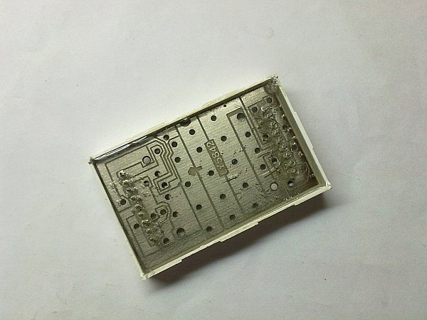
I tried giving 5v input to 2 pins at a time as was suggested, but while some combinations do not lead to any LEDs lighting up, some of them make 3 or four random ones to light up! It isn loose or faulty contact on my part because same thing happens every time. Im posting a picture of the circuitry that can be seen at the back of the panel. Does this make any sense to any of you? Am I to use this as a reference for wiring?
![]()
I tried giving 5v input to 2 pins at a time as was suggested, but while some combinations do not lead to any LEDs lighting up, some of them make 3 or four random ones to light up! It isn loose or faulty contact on my part because same thing happens every time. Im posting a picture of the circuitry that can be seen at the back of the panel. Does this make any sense to any of you? Am I to use this as a reference for wiring?
Sun Mar 20 2011, 02:06 am
Are you sure no pins are shorted together, perhaps with solder splashes.
Can you post examples of the front with LEDS lit up.
Are you using a limiting resistor and no more than five volts to test.
Even a short key press lasts a long time as far as a micro is concerned.
Using an interrupt or frequent polling allows us to read the key press
without needed to use a latch.
Can you post examples of the front with LEDS lit up.
Are you using a limiting resistor and no more than five volts to test.
if we are interfacing a push button, do we need a latch to keep the pressed input high
or just a pulse is enough?acaris1
Even a short key press lasts a long time as far as a micro is concerned.
Using an interrupt or frequent polling allows us to read the key press
without needed to use a latch.
[ Edited Sun Mar 20 2011, 02:21 am ]
Powered by e107 Forum System

Darrellciz
Thu Apr 18 2024, 11:07 am

Charlessber
Thu Apr 18 2024, 09:29 am

BartonSem
Thu Apr 18 2024, 04:56 am

DonaldKnown
Thu Apr 18 2024, 12:24 am

utaletxcyw
Wed Apr 17 2024, 10:21 am

Anthonyvab
Wed Apr 17 2024, 08:48 am

RobertCix
Wed Apr 17 2024, 06:46 am

Astorne
Tue Apr 16 2024, 08:52 pm