New age Car indicator system


Sun Mar 20 2011, 09:54 am
@ acaris1
connect its supply as u do
and upload a pic of front view of dot matrix
where leds is glowing as u say
connect its supply as u do
and upload a pic of front view of dot matrix
where leds is glowing as u say


Mon Mar 21 2011, 11:25 pm
Hello again, everyone!
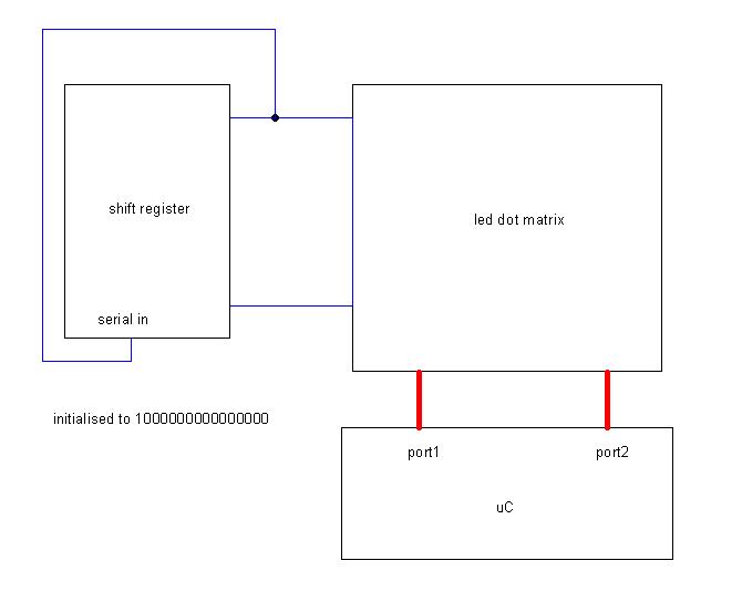
Sorry for bothering you all so much, but as I was going through the tips again, I was wondering how a counter can be used for the task. At that time I got it confused with a shift register. Here is a basic idea I have in mind- Shift reg initialised with any one bit 1 and rest 0 energises one row at a time, while at the same rate, the ports from uC give the bits of the column. We do this at a refresh period of less than 20ms and it looks like it is happening at the same time, right? Where do counters come in?
![]()
Sorry for bothering you all so much, but as I was going through the tips again, I was wondering how a counter can be used for the task. At that time I got it confused with a shift register. Here is a basic idea I have in mind- Shift reg initialised with any one bit 1 and rest 0 energises one row at a time, while at the same rate, the ports from uC give the bits of the column. We do this at a refresh period of less than 20ms and it looks like it is happening at the same time, right? Where do counters come in?
Tue Mar 22 2011, 08:57 am
@ acaris1
elaborate some more about ur problem
delay can be adjusted by hit and trial method
which counter ur asking
elaborate some more about ur problem
delay can be adjusted by hit and trial method
which counter ur asking
Tue Mar 22 2011, 10:56 pm
As for driving the 16*16 array I don't think you need the 8255.
Use simple counters, such as 4017s to drive each column in turn.
This only needs two pins from P0 or P3, allowing port 2 to drive the rows.
An 8255 will need at least one extra control line anyway.ExperimenterUK
The way Experimenteruk suggested.


Wed Mar 23 2011, 01:03 am
The 4017 is quite unusual, it is a counter but behaves a lot like a shift register.
To drive up to 20 rows /columns use two 4017s.
Connect the clock pins of both to one port pin.
Connect the reset of one directly to a second port pin.
Invert this reset line, (using a single transistor)
and connect to the second 4017's reset.
Pulse the clock line to step through one 4017's outputs
while the other is held in reset.
After ten pulses,flip the reset line to use the second 4017.
Every time you clock the 4017's change the pattern on ports 1 and 2.
Because any given LED is only on for 1/16 of the time
your display may be a bit dim so consider using less LEDs, say 10 * 10.
Thu Apr 28 2011, 04:57 pm
Hello everyone..sorry for the long absence. You guys were willing to help but I could not continue with the project due to personal reasons and emergencies.
Anyway coming to it now, I have decided that the time in hand is very less before submission and the idea has now changed slightly. I previously had planned on using a matrix of LEDs but now it is a 'projector' system wherein a stepper controls the symbol of the car indicator that needs to be projected and superbright LEDs project that slide on to the back of the car.
a total of 8 symbols will be used just as is shown above. I am attaching a basic code that I have written till now with some comments. Please tell me if this is okay. Thanks in advance.
org 0000h
ljmp main

ORG 0013H		   ; THIS INTERRUPT IS ACTIVATED WHEN ANY KEY IS PRESSED
LJMP CONORTURN

ORG 0003H         ;THIS INTERRUPT IS ACTIVATED BY THE STEERING WHEEL POSITION SENSOR
LJMP STEERSENSOR


ORG 0100H
MAIN:
MOV TMOD,#01H
MOV P0,0FFH
SETB EA
SETB EX1
SETB EX0
SJMP $
;MOV 12H,00H


 ; Subroutine bIstep to rotate stepper three steps left OR RIGHT, on the basis of PSW.5 flag
BISTEP:
	MOV R0,#0CH

BACKB:
    JB PSW.5, ROTR
    RL A
	SJMP HERE
	ROTR: RR A
    HERE:
	MOV P0,A
	ACALL DELAY
	DJNZ R0,BACKB
RET


 ; Delay Subroutine, 52000 uS
DELAY:
	MOV R1,#50H
BACKD:
	MOV R2,#255H
	DJNZ R2,$
	DJNZ R1,BACKD
RET

  ; Delay 2 subroutine, approximately 6 seconds
DELAY2:
    MOV R0,#7FH
	BACK:
	MOV TH0,#00H
	MOV TL0,#FFH
	SETB TR0
	HERE1: JNB TF0,HERE1
	CLR TF0
	CLR TR0
	DJNZ R0,BACK
RET


 ; Subroutine to calculate number of rotations required from current position and the direction in which it has to rotate

 STEPCAL:
	;R3 IS USED TO STORE THE CURRENT POSITION
	; R4 TO STORE NEW POSITION

	 MOV R5,A	;Store value of a in r5
	 MOV A,R3
	 SUBB A,04H	;Find difference between the current and new position

	 JNB ACC.7, DCOMPLE	 ;Check if difference is positive or negative
	 SETB PSW.5			 ;if it is negative set F0. F0 is to determine direction of rotation
     CPL A				 ;Find 2's complement of difference if it is negative
     INC A
     DCOMPLE:
	 ; To determine shortest way to reach new position
	 MOV R3,04H			 ;Move new position to R3. Therefore, new position is current position next time
	 MOV R4,A			 ;Move the difference obtained in previous step to R4
	 SUBB A,#04H		 ;Subtract 4 from the difference
	 JC NOCL			 ;See if diff is greater than 4 by checking carry bit and jump if 4 is greater
	 MOV A,#8H			 ;else we find mod 8.
	 SUBB A,04H			 ;Subtract the diff obtained initially from 8
	 CPL PSW.5			 ;Complement psw.5 as direction needs to be reversed
	 MOV R4,A			 ;R4 is stored with the value by which the motor needs to be rotated
     NOCL:				 ;At this stage R4 has the no of turns which motor needs to do.
		MOV A,R5
		RET

 ;ISR that decides if the pressed button is constant symbol ('L Board' or 'Caution!') or a turn symbol (Left/Right,U-turn, etc.)
 ; and takes the necessary action
org 0100h
CONORTURN:
MOV A,P0
ANL A,07H			  ; Mask lower bits
INC A				 ; Pencoder i/p is 0 to 7 but stepcal needs 1 to 8
MOV 12H,A
MOV R4,A
ACALL STEPCAL
SUBB A,#06H			   ; less than 6 =>
 turns, otherwise constant symbols. Use carry to determine
MOV A,12H
JNC NCONST
SETB PCON.3			    ; free flag to be used for indicating if keypress is a turn(0) or constant(1)

NCONST:
CJNE R4,#00H,TURNMOTOR	  ; R4=0 means the driver has pressed the same button twice in succesion
;CPL LED				  ; A subroutine to complement current state of light source. If the driver presses the same button twice
;                           before a turn, it means he wishes to switch it off. If it is done after the turn, it has to switch on.
                           ; therefore, we complement the current state of the light source.
TURNMOTOR:
ACALL BISTEP			   ; turn stepper to get the right symbol in front
;Switch on LED			   A subroutine to switch light source on. Yet to be written
RETI
;________________________________________________________________________________________________________

org 0150h
STSENSOR:
ACALL DELAY
JNB P3.2, RETISR
ACALL DELAY2
;Switch off LED				; Subroutine to switch off the light source. Yet to be written
RETISR: RETI
Powered by e107 Forum System

ChrisLub
Tue Apr 23 2024, 05:21 pm

Davidbab
Tue Apr 23 2024, 10:41 am

Richardrit
Tue Apr 23 2024, 09:54 am

HenryLaf
Mon Apr 22 2024, 03:50 pm

bleradrar
Mon Apr 22 2024, 06:38 am

ppu-pro_ka
Sun Apr 21 2024, 07:39 pm

Infewow
Sun Apr 21 2024, 06:30 pm

HumanTak
Sun Apr 21 2024, 12:26 pm