phase firing angle delay using 8051


the problem is when i plug out the interrupt pin, it keep executing the routine.
here is the code:
#include<reg52.h>

 sbit triac=P3^0;
 void cct_init(void);
 void initint0(void);

void delay(unsigned int count)
{
unsigned int i;
    while(count) {
        i = 115;
                while(i>
0) i--;
        count--;
}}

void cct_init(void)
 {
 P3=0x05;					 //triac is on when active low
 }


void initINT0(void)
 {
 IT0=0;
 EX0=1;
 EA=1;
 }


void external0_isr(void) interrupt 0
 {
 delay(4);
 triac=0;
 delay(1);
 triac=1;
 EA=0;
 EA=1;
 }

 void main(void)
 {
  cct_init();
  initINT0();
 while(1)
 {}

}
i tried to make half power delivery but its not working
[ Edited Fri Jan 25 2013, 01:13 pm ]


Are you sure your delay timer is correct.
If the crystal is 12mHz and is divided by 12, a clock cycle is 1uS.
That means
for(j=0;j<1275;j++);
is much more than 1mS.
Can you post your diagram ?
Are you sure your delay timer is correct.
If the crystal is 12mHz and is divided by 12, a clock cycle is 1uS.
That means
for(j=0;j<1275;j++);
is much more than 1mS.ExperimenterUK
i use 11.0592 mhz how should i set the proper one? honestly i dont have idea about 1275
what do you mean by diagram? the circuit? im outside now you can see my circuit in my other thread it just dont runs in proteus but in real time
but when i unplug the mcu cable in zcd, isr keep executed. is it because i have while(1) inside my isr?i want to use simple code to understand how it works. later on i wan to use if function based on adc reading.
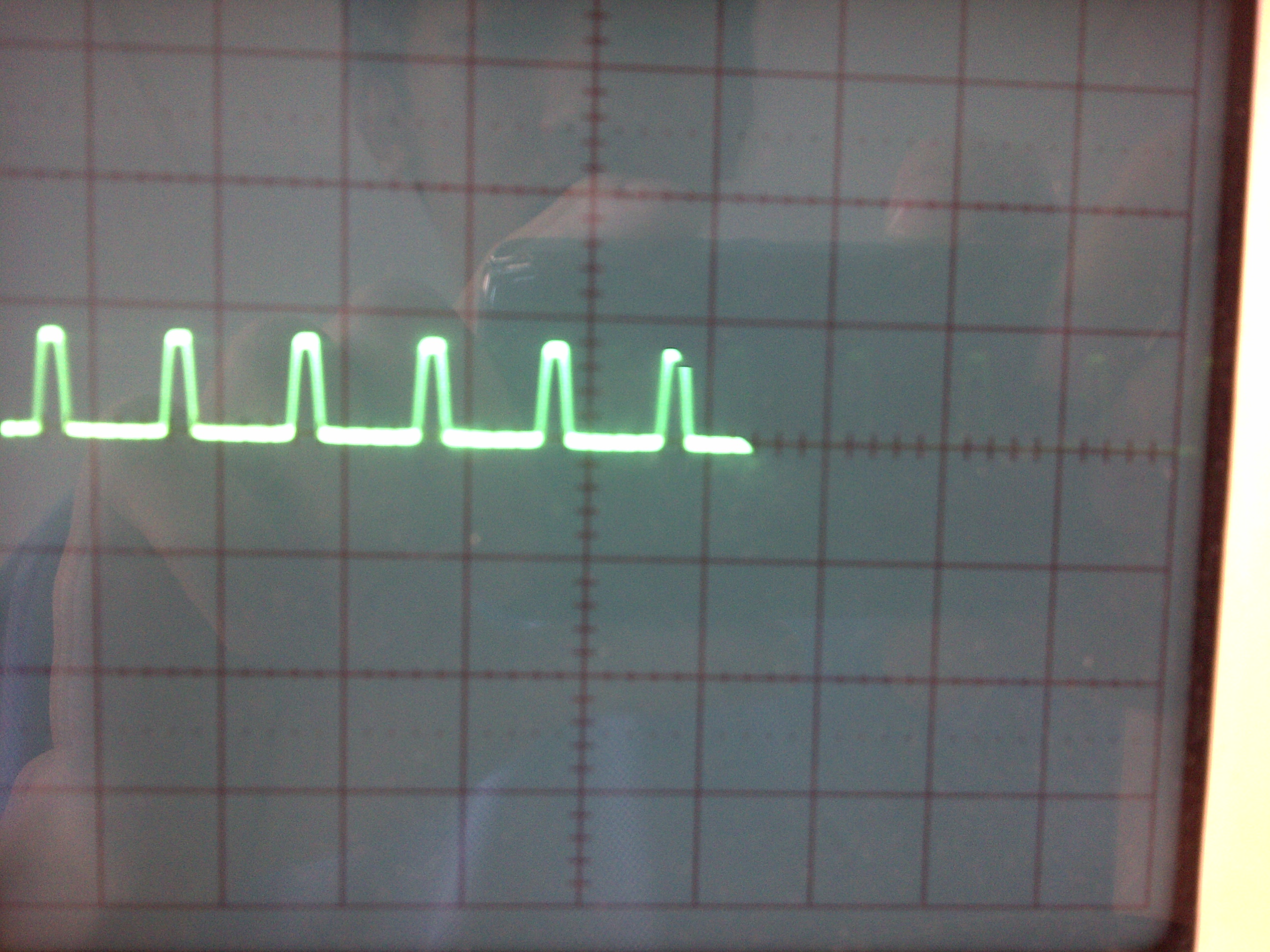
so the theory is zcd will goes high every 10mS. the length of the high zcd as seen on oscilloscope is 0.5mS in the left and 0.5mS in the right. so my half wave is roughly 9mS.
so if i want to get 50% power to my load, i have to delay 4/5mS then fire triac and turn triac off.if i dont use while(1) it only executes once. but i dont get it why it keep executing isr even when not interrupted.

but when i unplug the mcu cable in zcd, isr keep executed.bagusdj
With your posted code this should not happen.
It may be because P3.2 is floating, try connecting to Vcc when not connected to the ZCD circuit.
Keep all mains voltages well away form the low voltage circuitry.
so the theory is zcd will goes high every 10mS. the length of the high zcd as seen on oscilloscope is 0.5mS in the left and 0.5mS in the right.bagusdj
Don't forget that the interrupt is active low so will be triggered at the end of the pulse
0.5 mS into the cycle.
so if i want to get 50% power to my load, i have to delay 4/5mS then fire triac and turn triac off.bagusdj
That sounds about right.
However your code turns the triac on immediately.
Try this
void external0_isr(void) interrupt 0
{
delay(5);
triac=0; //triac on
delay(1);
triac=1; //triac off
}
Change the count in delay to get a better 1mS delay.
The exact value depends on how the compiler creates the code.
Change
for(j=0;j<1275;j++);
to
for(j=0;j<115;j++);
[ Edited Fri Jan 25 2013, 02:28 am ]
sorry, my bad. the problem is the connection of cable that connects P3^2 to interrupt source. i replace it and it runs normally.
i tried using this attached program, and i get around 131Vac. i use multimeter,so it is rms i suppose, is it?
from delay 4mS i get that value. the voltage is decreased.
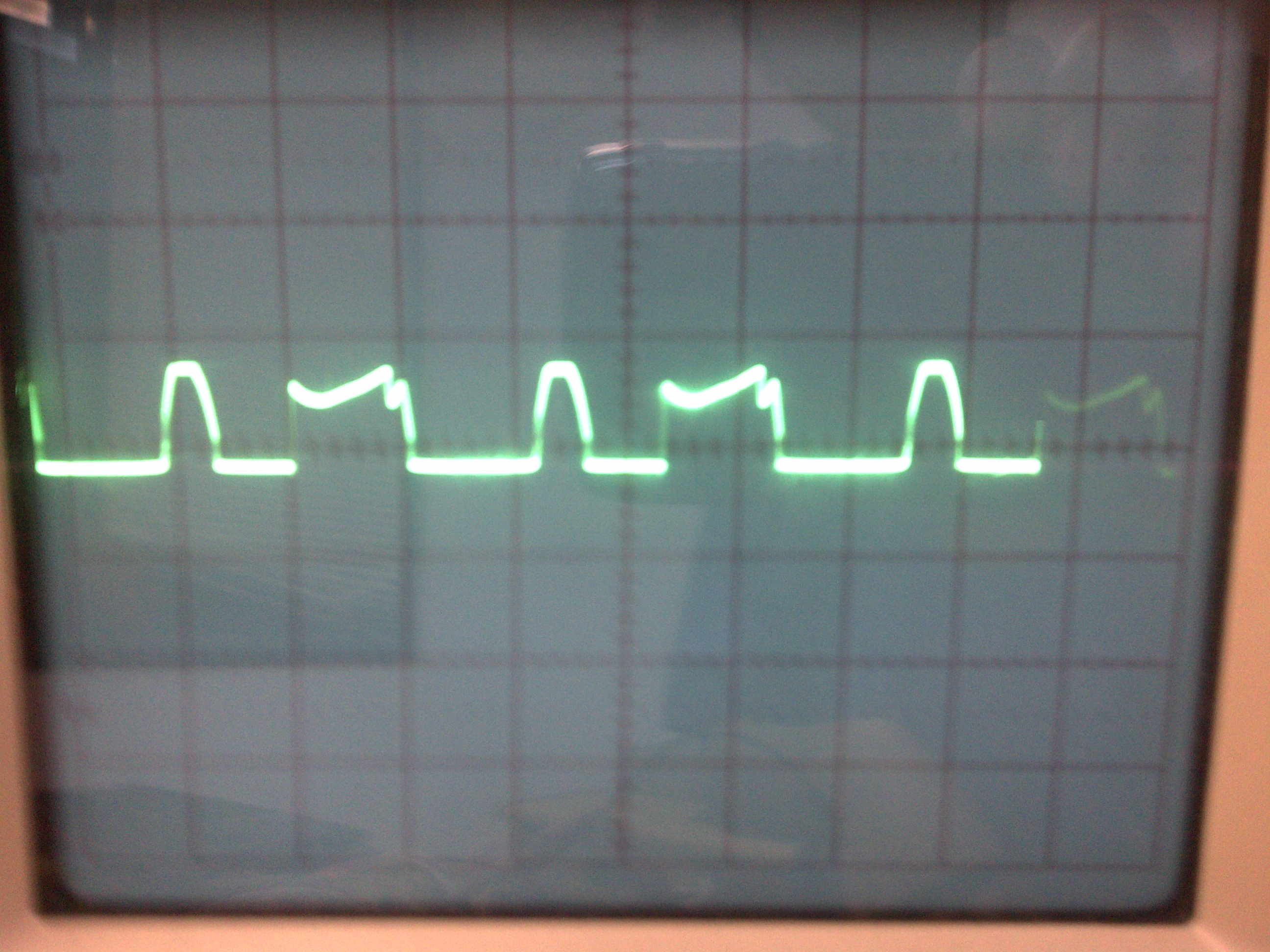
i would like to ask, did i done something wrong here if you guys look at the picture? the picture that i had with 4mS delay.

[ Edited Fri Jan 25 2013, 01:14 pm ]


try to use this delay or use timer of 8051 for accuracy
void DelayMs(unsigned int count)
{  // mSec Delay @ 11.0592 Mhz
    unsigned int i;
    while(count) {
        i = 115;
		while(i>
0) i--;
        count--;
    }
}
i get around 131Vac. i use multimeter,so it is rms i suppose, is it?
yes it should be rms value
FYI the code in 1st post is updated.bagusdj
It is better not to change a post if it makes the replies hard to understand.
Better to post an updated version of your code
i would like to ask, did i done something wrong here if you guys look at the picture? the picture that i had with 4mS delay.bagusdj
The display looks odd, is there a problem with the scope, or the triggering ?
FYI the code in 1st post is updated.bagusdj
It is better not to change a post if it makes the replies hard to understand.
Better to post an updated version of your code
i would like to ask, did i done something wrong here if you guys look at the picture? the picture that i had with 4mS delay.bagusdj
The display looks odd, is there a problem with the scope, or the triggering ?ExperimenterUK
im sorry,my bad.
my transformer is single tap. i powered my 220 load by jumper the backside of trafo (0&220), the front side (0&9) is for my adapter. if the configuration like this, the zero cross pulse is normal. but i cant see the load's wave since the scope cannot show 220v properly (wave is too huge).
so what i did is to change my 220 load into front side of trafo (0&15) to get the smaller wave form,so scope can display it. the load wont run of course but i think the clipped voltage would occur. i check the zero crossing pulse and it is crippled and the load wave become like that.
my scope probe is on + and - of the load. i think moving the power source of load to front side is the cause. how can i display it correctly?
Can you post a sketch of your circuit and oscilloscope connections.
You should be able to run the ZCD and triac circuits from a low voltage source such as a 50v transformer,
is that what you are doing ?
Can you post a photo of the signals being fed into the opto-isolator
and say what the oscilloscope time scale is.
[ Edited Tue Jan 29 2013, 07:53 am ]


