want ir LONG RANGE ciruit for reflected type ir sensor


Sat Jul 06 2013, 01:17 am
#include <REG2051.H>

void delay1(void);
// Infrared drive on P1.0
sbit irq_indicator=P3^7;
sbit ir=P1^7;
int a;
int c, n;

void delay (unsigned int count) // @ 11.0592 MHz
{
unsigned int i;
while(count) {
i = 115;
while(i>
0) i--;
count--;
}
}

void externalIrq_isr () interrupt 0
{
irq_indicator=1; //detection indicator on
}

void timer0_isr () interrupt 1
{
ir= ~ir;
a++;
}

void main ()
{
irq_indicator=0;
TMOD = 0X02;
TL0 = 0xf4;
TH0 = 0xf4;
IE = 0x83;
while(1)
{
TR0=1;
while(a < 80); //output 40 cycles
TR0=0; //timer off
ir=0; //reset count, Infrared off
a=0;
delay(8); //60mS gap between pulses
irq_indicator=0; //detection indicator off
} //end while
}
i did little modification to get output at p1^7 but dis code also didnt work for me..!
i have shifted the let to collector side changed the tsop also..but bad luck is all i got oll the time..:(
[ Edited Sat Jul 06 2013, 01:22 am ]


Sat Jul 06 2013, 02:19 am
There is not enough time in the timer handler to increment an integer (16 bits).
Change 'a' to a char and it will work.
Change 'a' to a char and it will work.
[ Edited Sat Jul 06 2013, 02:20 am ]
Sat Jul 06 2013, 02:22 am
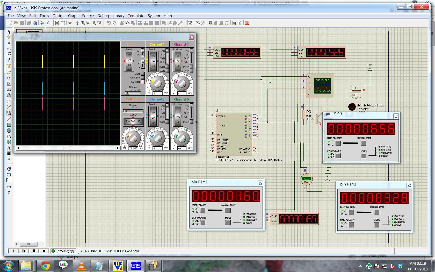
and one thing more @experiment uk: the code u provided me really thnxs for that but y at every pin frequency coming out to b different look at the picture..!
![]()
at what pin i should connect my ir led acc to ur code..!
at what pin i should connect my ir led acc to ur code..!
[ Edited Sat Jul 06 2013, 03:00 am ]
Sat Jul 06 2013, 02:25 am
Change 'a' to a char and it will work
should i use unsigned long int..?
Sat Jul 06 2013, 03:01 am
#include <REG2051.H>

void delay1(void);
// Infrared drive on P1.0
sbit irq_indicator=P3^7;
sbit ir=P1^7;
char a;
int c, n;

void delay (unsigned int count) // @ 11.0592 MHz
{
unsigned int i;
while(count) {
i = 115;
while(i>
0) i--;
count--;
}
}

void externalIrq_isr () interrupt 0
{
irq_indicator=1; //detection indicator on
}

void timer0_isr () interrupt 1
{
ir= ~ir;
a++;
}

void main ()
{
irq_indicator=0;
TMOD = 0X02;
TL0 = 0xf4;
TH0 = 0xf4;
IE = 0x83;
while(1)
{
TR0=1;
while(a < 80); //output 40 cycles
TR0=0; //timer off
ir=0; //reset count, Infrared off
a=0;
delay(8); //60mS gap between pulses
irq_indicator=0; //detection indicator off
} //end while
}
still not working..:(

Sat Jul 06 2013, 10:28 am
your pulse width is too small as I see in the simulation. And regarding different frequency, It looks like a "bug in proteus?" As I see, first pulse counter gives one value and other one is half of first one and last is half of second.. its confusing. try to zoom out from your scope and see if all the pulses match.
I think you need to reconsider your IR circuit to get a better range. I gave few websites that talk about long range IR about 10ft. did you look at them?
I think you need to reconsider your IR circuit to get a better range. I gave few websites that talk about long range IR about 10ft. did you look at them?
Sat Jul 06 2013, 08:33 pm
yes sir i have already been through dat sites befor you send me link they are doing it using using same thing using 555timer and as u seen m doing it same using controller but i am not able to achieve range..!
Sat Jul 06 2013, 11:41 pm
your pulse width is too small as I see in the simulation.Ajay Bhargav
These pulses are trains of 40 cycles which is in the middle of the range suggested in the
data sheet (between 10 and 70 cycles).
And regarding different frequency, It looks like a "bug in proteus?" As I see, first pulse counter gives one value and other one is half of first one and last is half of second.Ajay Bhargav
In that version of the code, P1 acted as a counter.
P1.0 outputs at 38kHz,P1.1 outputs at 19 kHz etc.
It was a simple (some might say brilliant
 ) way to save machine cycles during the TIMER0 interrupt.
I think you need to reconsider your IR circuit to get a better range. I gave few websites that talk about long range IR about 10ft. did you look at them?Ajay Bhargav
yes sir i have already been through dat sites befor you send me link they are doing it using using same thing using 555timer and as u seen m doing it same using controller but i am not able to achieve range..!lucky6772
I'm sure what you have is a hardware fault.
If you have an oscilloscope (to set the frequency), it is worth building the transmitter
from that website as a piece of test equipment.
Use different components and a separate power supply.
Meanwhile post the latest version of your circuit diagram, including the power supply
arrangement.
Remember that not Infrared diodes are the same.
As noted on that site, some are just poor quality or not the right wavelength for
the TSOP.
[ Edited Thu Jul 11 2013, 01:05 am ]
Sun Jul 07 2013, 01:36 am
P1.0 outputs at 38kHz,P1.1 outputs at 19 kHz etc.
so acc to u at which pin i should connect output to the IR led..?
Sun Jul 07 2013, 01:52 am
P1.0 outputs at 38kHz,P1.1 outputs at 19 kHz etc.
so acc to u at which pin i should connect output to the IR led..?lucky6772
For the code I posted, drive the IR led from P.0
However you changed the code to use P.7
Powered by e107 Forum System

Clydehet
Wed May 01 2024, 06:44 pm

Davidoried
Wed May 01 2024, 06:11 pm

KevinTab
Sun Apr 28 2024, 05:35 am

Tumergix
Sun Apr 28 2024, 12:59 am

StevenDrulk
Sat Apr 27 2024, 08:47 pm

StephenHauct
Sat Apr 27 2024, 09:38 am

Adamsaf
Sat Apr 27 2024, 07:12 am

Robertphype
Sat Apr 27 2024, 12:23 am