Difference between revisions of "UART Communication Tutorial" From Rikipedia Embedded Wiki
Ajay Bhargav (talk | contribs) (Intial commit for tutorial) |
(No difference)
|
Revision as of 16:28, 25 February 2015
UART (Universal Asynchronous Receiver Transmitter) or USART (Universal Synchronous Asynchronous Receiver Transmitter) are one of the basic interface which you will find in almost all the controllers available in the market till date. This interface provide a cost effective simple and reliable communication between one controller to another controller or between a controller and PC.
RS-232 Basics
RS-232 (Recommended Standard 232) is a standard for serial binary data signals connecting between a DTE (Data terminal equipment) and a DCE (Data Circuit-terminating Equipment).
Voltage Levels
The RS-232 standard defines the voltage levels that correspond to logical one and logical zero levels. Valid signals are plus or minus 3 to 25 volts. The range near zero volts is not a valid RS-232 level; logic one is defined as a negative voltage, the signal condition is called marking, and has the functional significance of OFF. Logic zero is positive, the signal condition is spacing, and has the function ON. So a Logic Zero represented as +3V to +25V and Logic One represented as -3V to -25V.

RS232 Voltage Levels
RS-232 Level Converters
Usually all the digital ICs works on TTL or CMOS voltage levels which cannot be used to communicate over RS-232 protocol. So a voltage or level converter is needed which can convert TTL to RS232 and RS232 to TTL voltage levels. The most commonly used RS-232 level converter is MAX232. This IC includes charge pump which can generate RS232 voltage levels (-10V and +10V) from 5V power supply. It also includes two receiver and two transmitters and is capable of full-duplex UART/USART communication.
Fig A. - MAX232 Pin Description

Fig B. - MAX232 Typical Connection Circuit
MAX232 Interfacing with Microcontrollers
To communicate over UART or USART, we just need three basic signals which are namely, RXD (receive), TXD (transmit), GND (common ground). So to interface MAX232 with any microcontroller (AVR, ARM, 8051, PIC etc..) we just need the basic signals. A simple schematic diagram of connections between a microcontroller and MAX232 is shown below
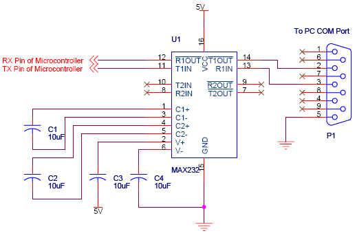
MAX232 Connections with Microcontroller
See Also
- 8051 UART/Serial Communication Tutorial
- 8051 Software UART Tutorial
- AVR UART/Serial Communication Tutorial
- GPS Receiver Interfacing over UART Tutorial
- GSM Modem Interfacing over UART Tutorial
Help & Queries
If you have any queries, doubts or feedback on this tutorial please share in our discussion forum.