best gsm and gps modules for arduino


yes ofcourse thats possible but all I wanted to say was.. you did not need a board extra board, you could have done it taking wires directly from GSM and GPS boards.
but now problem here is.. have one max232 board and you need two serial outs. which is not possible with current board. They might have given Test points but only one is connected on the RS232 out. hope you are getting my point. So its better you take wires from GSM and GPS board as for GSM you have TTL out directly and for GPS you can take out yourself or use max232 board for GPS atleast.
NOTE: check voltage levels of all devices before making any final connections
Ajay Bhargav
ok, I got your point.
For the GPS board, then I think should solder extra wires below the pcb board only for the tx and rx of the gps module (Holux) .
Sorry to bother you, You have mentioned "or use max232 board for GPS atleast"
How do I connect the GPS module to arduino board using MAX 232 ?
As the GPS board only a serial com port (rs 232).
[ Edited Wed Feb 06 2013, 01:27 am ]


i meant connect the other way.. like connect RS232 of GPS to RS232 of Max232 board, then take TTL signals to arduino. so you dont have to take wires from GPS board and connect test points to arduino.Ajay Bhargav
I am not so familiar with these max 232 boards. so please help me out
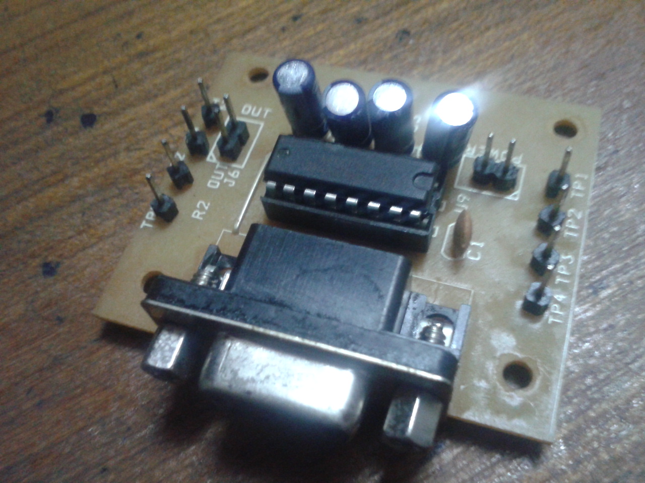
I have connected the rs 232's (gps and max ) using a male to male connector.
I have posted pic's below of max 232.
No, from where do I take the output ?
Do, I have to give any inputs to it?

I believe its easier to connect GPS board directly to arduino than going with this max232 board. coz this board itself is a mystery. and you need to make extra connections for power too. which can be a pain. so best way is to connect it directly. rest is your decision how you want to go ahead.
I dont know why they sell such boards with no information. They seems to make only money out of it. anyways you have to download datasheet of Max232 and use multimeter find where to connect power and other signals and which signal goes where.
I believe its easier to connect GPS board directly to arduino than going with this max232 board. coz this board itself is a mystery. and you need to make extra connections for power too. which can be a pain. so best way is to connect it directly. rest is your decision how you want to go ahead.Ajay Bhargav
IF a use board like the one below, I can connect the rx and tx pins of max to tx and rx of arduino, right? (ignoring cts and rts signals), after having connected the 2 rs 232 pins using a male-male cable.
http://www.mikroe.com/img/development-tools/accessory-boards/communication/max232-connector/preview/max232_thumb01.png
[ Edited Wed Feb 06 2013, 12:50 pm ]
 When I was in bangalore i used to make everything myself, no wonder I know SP road of Bangalore
  I soldered all kind of boards. even the most complicated ones. it was real fun, real learning.
I do not understand why you want to use max232 anyways. and max232 board is so simple you can make one yourself, stop spending money for simple things. You are in bangalore, silicon city of India. still you buy ready stuffAjay Bhargav
Ya, i will make my own max 232 board. Thats the best thing to do to avoid any confusions.
But, I cannot make a gps board or gsm board.
I do not understand why you want to use max232 anyways. and max232 board is so simple you can make one yourself, stop spending money for simple things. You are in bangalore, silicon city of India. still you buy ready stuffAjay Bhargav
Or perhaps I can do the most easiest and smartest thing.
I can solder two wires from beneath the board (for rx and tx) of gps module (ttl ) as i know which pin is what from data sheet and connect to tx and rx of arduino respectively. But i would leave the max ic intact on the board itself and leave the rs 232 port on the board unused , but power the gps module using 12 v adapter provided on board.
What do you think?
I can solder two wires from beneath the board (for rx and tx) of gps module (ttl ) as i know which pin is what from data sheet and connect to tx and rx of arduino respectively. But i would leave the max ic intact on the board itself and leave the rs 232 port on the board unused , but power the gps module using 12 v adapter provided on board.
What do you think?bobdxcool
Thats what I was trying to say, no need to use max232. just connect gps as well as gsm module directly to arduino board. so you need to decide which board you want to connect to hardware uart and which one to softuart. This depends on type of application and criticality of task. I mean what is more important to you in respect to the application of device.
NOTE: with soft uart you can use any two pins as rx and tx so no compulsion.
I can solder two wires from beneath the board (for rx and tx) of gps module (ttl ) as i know which pin is what from data sheet and connect to tx and rx of arduino respectively. But i would leave the max ic intact on the board itself and leave the rs 232 port on the board unused , but power the gps module using 12 v adapter provided on board.
What do you think?bobdxcool
Thats what I was trying to say, no need to use max232. just connect gps as well as gsm module directly to arduino board. so you need to decide which board you want to connect to hardware uart and which one to softuart. This depends on type of application and criticality of task. I mean what is more important to you in respect to the application of device.
NOTE: with soft uart you can use any two pins as rx and tx so no compulsion.Ajay Bhargav
The modules wont be damaged if use board power supply and leave the max 232 part and other parts unused on the board(directly taking the output from modules by soldering ires below), right?
And, the max 232 tx and rx ports wont cause any interference (signals) to gps and gsm modules , right?
This is because although I am not using the rs 232 on the board, as per the pcb the gps and gsm modules (sim 300) are connected to max 232 ic and I will connect wires somewhere in between.
[ Edited Thu Feb 07 2013, 01:53 am ]


