Discussion in "Project Help" started by SANATH EMBEDDED Feb 3, 2009.


Tue Feb 03 2009, 03:24 pm
 ya ya sure PDI :-) I pray daily Lord Shiva to give me the source code of this project. might be he is also scratchng his head lk me :mad
 Ya now coming to Active, Reactive, & Apparent power ( looks lk sm 3D parameters
) 
If I am not wrong, the Active power is nothing but the actual power consumed and it is measured in terms of Killo-watt hours (KWh). and when the load contains reactive elements such as capacitance & inductance , because of that Current will be out of phase with the voltage by an angle. So as a result some kind of reactance is introduced into the line and the power associated with that is the Reactive power . and is measured in VAR Hours.:D and the Apparent power is the vector sum of active power & Reactive power & is measured in VA Hours. Practically I need to check out how this reactive power comes into picture, if there is no reactive elements in load then wat happens

then the next thing why I was not able to get the Active Power Pulsed o/p when I had given the Single phase to ADE. Since in ADE each phase is independent I think it has to work with single phase. The main reason is
The output from the DFC is divided down by a pair of frequency division registers before being sent to the APCF pulse output. Namely, APCFDEN/APCFNUM pulses are needed at the DFC output before the APCF pin outputs a pulse.
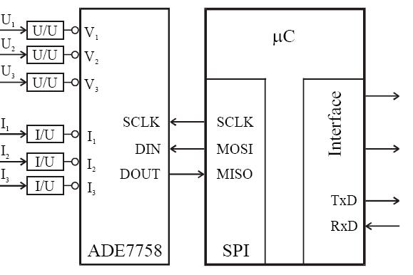
So until & unless I do the SPI Communication with ADE7758 for initializing the internal registers there is no other way I can check out the functionality. :-)
Powered by e107 Forum System

RonaldNak
Thu May 09 2024, 07:45 pm

Jamescon
Thu May 09 2024, 12:52 pm

RobertSkats
Thu May 09 2024, 10:23 am

hvCar
Thu May 09 2024, 05:53 am

DJGlido
Wed May 08 2024, 09:28 pm

migCar
Wed May 08 2024, 04:48 pm

TimmyJup
Wed May 08 2024, 12:22 am

Shawnarows
Tue May 07 2024, 10:16 pm