sim300cz and atmega16L


Sun Mar 08 2009, 03:41 am
bundle of thanks to everyone...
sim300cz is communicating with atmega perfectly...
we will be needing further help in future...
thanks again
reagards
usman
sim300cz is communicating with atmega perfectly...
we will be needing further help in future...
thanks again
reagards
usman


 post if any help needed

Thu Mar 19 2009, 09:10 pm
Hello guys, I am new in the forum, and actually this is my first post. I came across with it because I am having the same problem with the SIM340 that is like the SIM300 but Quad band. They share the same logical pin out and stuff but have different form factor.
I am using the SIM300 EVB module to test, which is a evaluation board designed for SIM300 but it is also compatible with SIM340. The board has most of the signals from the SIM340 chip connected to headers pins so that I can have access to the chip pins directly so there's no need to build a special board.
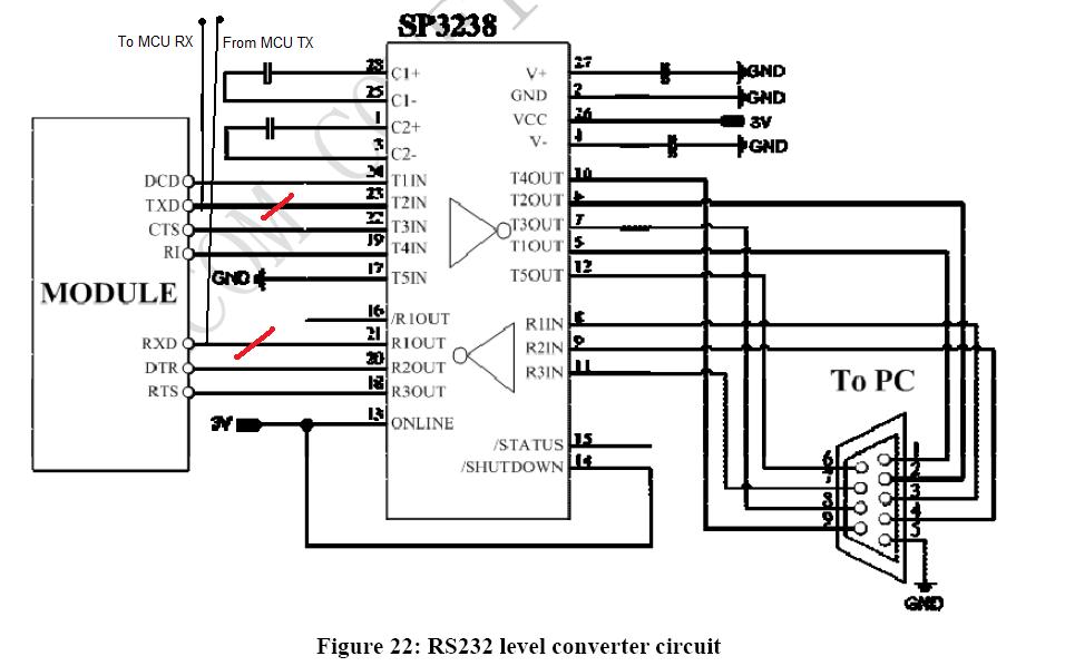
The board has the pins connected to a SP3238 rs-232 tranceiver to connect to the PC, I have tested this interface and works fine, but when I connect the microcontroller TX,RX directly to the TX,RX , the SIM340 does not respond.
I think that may be a signal level problem, my microcontroller is operating at 3.3 V, I have used also a FTDI232 USB to serial cable that operates at 0-3.3V logic level to connect the PC to the SIM340 and does not respond either.
What do you think, what do you recommend to me?
I am using the SIM300 EVB module to test, which is a evaluation board designed for SIM300 but it is also compatible with SIM340. The board has most of the signals from the SIM340 chip connected to headers pins so that I can have access to the chip pins directly so there's no need to build a special board.
The board has the pins connected to a SP3238 rs-232 tranceiver to connect to the PC, I have tested this interface and works fine, but when I connect the microcontroller TX,RX directly to the TX,RX , the SIM340 does not respond.
I think that may be a signal level problem, my microcontroller is operating at 3.3 V, I have used also a FTDI232 USB to serial cable that operates at 0-3.3V logic level to connect the PC to the SIM340 and does not respond either.
What do you think, what do you recommend to me?
Thu Mar 19 2009, 10:48 pm
first of all donot use usb to serial cable, instead use serial to serial canle...i am also facing some problem in using usb to serial cable.
Thu Mar 19 2009, 10:59 pm
Yes I used the serial interface that comes in the board, it has the raw TX,RX pins and also has a RS232 interface using a tranceiver. Using the RS232 interface everything is fine but when I try to use the raw pins, I get no reponse.
Fri Mar 20 2009, 02:00 am
do not connect controller + PC at the same time otherwise you wont get any response. for raw communication too. you need atleast rx tx and GND dont forget ground pin coz communication wont work without that.
if you still face problem you can post your schematic here i can check it.
if you still face problem you can post your schematic here i can check it.
Fri Mar 20 2009, 02:19 am
Yes, I am using the rx,tx, and gnd pins, you can see the schematics at http://www.microchip.ua/simcom/GSM-GPRS-GPS/SIM340/SIM340E_HD_V1.01.pdf
Sat Mar 21 2009, 07:42 pm
WHEN I CONNECT THE SIM300 I GET THESE MESSAGES:
"
RDY
+CFUN: 1
+CPIN: READY
Call Ready
"
i've used commands:
AT
AT+CMGF=1;
AT+CMGS="+92....." ->TO SEND MESSAGE TO MY NUMBER FROM SIM300CZ.
AT+CMGR=3 -> TO RECEIVE MESSAGE FROM MY CELL PHONE. "3" SHOWS LOCATION OF MESSAGE STORED IN SIM300CZ.
ALL THESE COMMANDS ARE USED IN COMMUNICATING SIM300CZ AND HYPERTERMINAL.
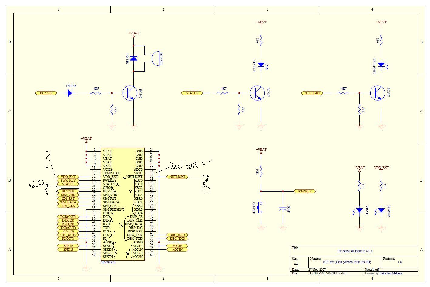
I M ALSO ATTACHING PIC OF SIM300(SHOWING WHICH PINS I'VE USED)
usman1947
What circuit are you using between the SIM300 and the microcontroller? I can't even get the RDY
+CFUN: 1
+CPIN: READY
Call Ready
Sat Mar 21 2009, 09:16 pm
do not connect controller + PC at the same time otherwise you wont get any response. for raw communication too. you need atleast rx tx and GND dont forget ground pin coz communication wont work without that.
if you still face problem you can post your schematic here i can check it.Ajay
Yes thanks for the advice, I actually have the circuit like in this picture, the red lines means that I cut the RX,TX connections to the tranceiver, so the tranceiver should not affect it... and I am connecting it to the MCU as showed... I can not even receive the initial bytes...
Powered by e107 Forum System

KevinTab
Sun Apr 28 2024, 05:35 am

Tumergix
Sun Apr 28 2024, 12:59 am

StevenDrulk
Sat Apr 27 2024, 08:47 pm

StephenHauct
Sat Apr 27 2024, 09:38 am

Adamsaf
Sat Apr 27 2024, 07:12 am

Robertphype
Sat Apr 27 2024, 12:23 am

ktaletrryp
Fri Apr 26 2024, 10:55 pm

Robertrip
Fri Apr 26 2024, 11:20 am