Color Sensor
Discussion in "Electronics" started by Ûž TPS Ûž Jan 3, 2008.


Thu Jan 03 2008, 12:22 am

Colour sensor is an interesting project for hobbyists. The cir- cuit can sense eight colours, i.e. blue, green and red (primary colours); magenta, yellow and cyan (secondary colours); and black and white. The circuit is based on the fundamentals of optics and digital electronics. The object whose colour is required to be detected should be placed in front of the system. The light rays reflected from the object will fall on the three convex lenses which are fixed in front of the three LDRs. The convex lenses are used to converge light rays. This helps to increase the sensitivity of LDRs. Blue, green and red glass plates (filters) are fixed in front of LDR1, LDR2 and LDR3 respectively. When reflected light rays from the object fall on the gadget, the coloured filter glass plates determine which of the LDRs would get triggered. The circuit makes use of only ‘AND’ gates and ‘NOT’ gates.
When a primary coloured light ray falls on the system, the glass plate corresponding to that primary colour will allow that specific light to pass through. But the other two glass plates will not allow any light to pass through. Thus only one LDR will get triggered and the gate output corresponding to that LDR will become logic 1 to indicate which colour it is. Similarly, when a secondary coloured light ray falls on the system, the two primary glass plates corres- ponding to the mixed colour will allow that light to pass through while the remaining one will not allow any light ray to pass through it. As a result two of the LDRs get triggered and the gate output corresponding to these will become logic 1 and indicate which colour it is.
When all the LDRs get triggered or remain untriggered, you will observe white and black light indications respectively. Following points may be carefully noted :
1. Potmeters VR1, VR2 and VR3 may be used to adjust the sensitivity of the LDRs.
2. Common ends of the LDRs should be connected to positive supply.
3. Use good quality light filters.
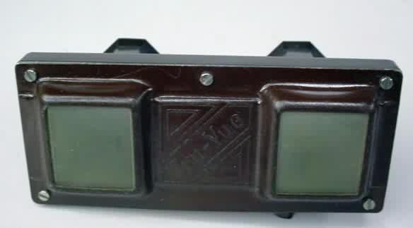
The LDR is mounded in a tube, behind a lens, and aimed at the object. The coloured glass filter should be fixed in front of the LDR as shown in the figure. Make three of that kind and fix them in a suitable case. Adjustments are critical and the gadget performance would depend upon its proper fabrication and use of correct filters as well as light conditions
ajay_bhargav, Sunrom like this.


Thu Jan 03 2008, 02:11 am
is this color detector hard to make?
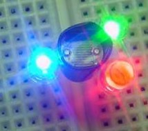
i saw in one project.. students using LED for color detection.. something like that.. i will search for link will show u.. it was really interesting.. i still did not get how did they do that... will share it with you..
i saw in one project.. students using LED for color detection.. something like that.. i will search for link will show u.. it was really interesting.. i still did not get how did they do that... will share it with you..
Thu Jan 03 2008, 10:32 am
not really but some times it can make you :mad  use convex lance of ordenory film strips showing toys like i had in my "BACHPAN" (Childhood ) for watching tajmahal ,lal quila, kutub minar etc... oh- i really miss that sweet time of my childhood :-s
they have shorter focal length
![]()
and i am also interested in" project.. students using LED for color detection" :-)
use convex lance of ordenory film strips showing toys like i had in my "BACHPAN" (Childhood ) for watching tajmahal ,lal quila, kutub minar etc... oh- i really miss that sweet time of my childhood :-s they have shorter focal length
and i am also interested in" project.. students using LED for color detection" :-)
Thu Jan 03 2008, 12:29 pm

Tue Mar 04 2008, 02:05 am
[ Edited Tue Mar 04 2008, 02:06 am ]
Powered by e107 Forum System

KevinTab
Sun Apr 28 2024, 05:35 am

Tumergix
Sun Apr 28 2024, 12:59 am

StevenDrulk
Sat Apr 27 2024, 08:47 pm

StephenHauct
Sat Apr 27 2024, 09:38 am

Adamsaf
Sat Apr 27 2024, 07:12 am

Robertphype
Sat Apr 27 2024, 12:23 am

ktaletrryp
Fri Apr 26 2024, 10:55 pm

Robertrip
Fri Apr 26 2024, 11:20 am