[SOLVED] Help needed for making "Android Controlled robot"


@ExperimenterUK & Androswap, Please tell me how could i check if my Bluetooth Module is working using Led (or some other method other than connecting it to the PC serial port as i don't have "PC to 8051 demo board having MAX 232").jasmeet_singh
I already answered that question ,in detail,in my first reply.
It also answers Ajay's point, that is , that rx on the Bluetooth module should connect to
rx on the 8051.


@ExperimenterUK & Androswap, Please tell me how could i check if my Bluetooth Module is working using Led (or some other method other than connecting it to the PC serial port as i don't have "PC to 8051 demo board having MAX 232").jasmeet_singh
I already answered that question ,in detail,in my first reply.
It also answers Ajay's point, that is , that rx on the Bluetooth module should connect to
rx on the 8051.ExperimenterUK
You suggested to connect LED on Rx and Tx , but i have these voltages on pin: RxD = 2.97 v, TxD = 0 v of buetooth module . I think the LED connected on RxD will glow. So i should connect RxD of bluetooth module to Rx of controller. I connected This way, but still it doesn't work.
Today i have built max232 serial port module. Can you Please give details, how could could i check my bluetooth module. @Androswap mentioned to use Flash magic terminal.. Can you give me detailed instructions. And if there comes error in its baud rate how could i correct it.
Thanks.
You suggested to connect LED on Rx and Tx , but i have these voltages on pin: RxD = 2.97 v, TxD = 0 v of buetooth module . I think the LED connected on RxD will glow. So i should connect RxD of bluetooth module to Rx of controller. I connected This way, but still it doesn't work.
Today i have built max232 serial port module. Can you Please give details, how could could i check my bluetooth module. @Androswap mentioned to use Flash magic terminal.. Can you give me detailed instructions. And if there comes error in its baud rate how could i correct it.
Thanks.jasmeet_singh
UPDATE:
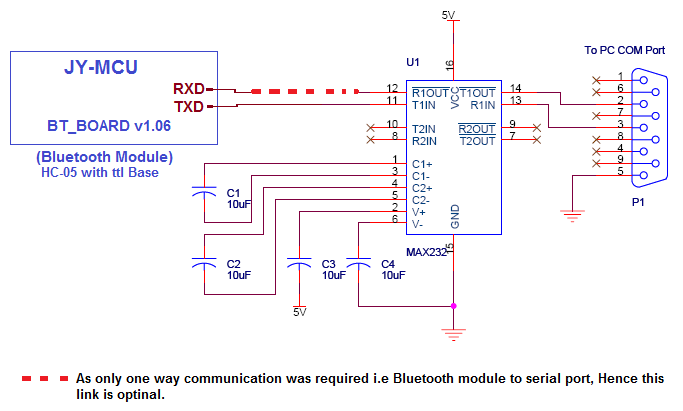
I connected my Bluetooth module (HC-05 JY-MCU [BT_BOARD v1.06]) to serial interface RS232 as shown below. I ahve connected on TXD pin of Bluetooth modulet to PIN11 of MAX232.
Using RealTerm : Serial Capture Program i was able to receive the ASCII codes on PC. Hence my Bluetooth Module is Working Fine.
So based on this observation I think i should connect TXD pin of Bluetooth Module to RXD[PIN3.0] of controller. But when connect like this , I was not able to get desired out put on PORT2. I have checked the controller Ports by giving Dummy output to PORT1, And there the output is correct.
CODE:
ORG 0000H					// Code Segment Start at 0000H
MOV P1,#45H					// Initialize PORT1
MOV P3,#00H					// Initialize PORT3
	MOV P2,#80H					// Initialize PORT2
	MOV TMOD,#20H				// SET TMOD register For TIMER 1 in MODE 2 (Auto Reload)
	MOV TH1,#-3					// SET Baud Rate to 9600
	MOV SCON,#50H			   	// 8-bit, 1 stop, REN enabled
	SETB TR1					// start TIMER 1
HERE:
	JNB RI,HERE					// Wait for char to come in
	MOV A,SBUF				   	// saving incoming byte in A
	CLR RI						// get ready to receive next byte
	CJNE A,#'U',ONE 			// Compare it to U (Up movement) If not equal to U the jump to ONE otherwise
	MOV P2,#89H					// Send 89H to PORT2 for upward movment
	SJMP HERE					// Jump to HERE for  next command character
ONE:
	CJNE A,#'D',TWO				// Compare it to D (down movement) If not equal to U the jump to two otherwise
	MOV P2,#86H					// Send 86H to PORT2 for upward movment
	SJMP HERE				   	// Jump to HERE for  next command character
TWO:
	CJNE A,#'R',THREE		   	// Compare it to D (Right movement) If not equal to U the jump to three otherwise
	MOV P2,#8AH				   	// Send 8AH to PORT2 for upward movment
	SJMP HERE				   	// Jump to HERE for  next command character
THREE:
	CJNE A,#'L',FOUR			// Compare it to D (Left movement) If not equal to U the jump to four otherwise
	MOV P2,#85H					// Send 85H to PORT2 for upward movment
	SJMP HERE					// Jump to HERE for  next command character
FOUR:
	CJNE A,#'C',HERE			// Compare it to D (Stop the movement) If not equal to U the jump to Here otherwise
	MOV P2,#00H					// Send 80H to PORT2 for upward movment
	SJMP HERE					// Jump to HERE for  next command character
	END						// CODE  segement Ends
Can you please check if there is any problem with the code.
Thanks.
[ Edited Mon Apr 28 2014, 11:48 am ]

;MOV P3,#00H
You should never modify port 3 when using uart. comment the below line and try again.;MOV P3,#00Hajay_bhargav
OH!!

It was there in the code file that you have uploaded on the project page.
Can you please simulate the correct code in KEIL. I don't know how to simulate UART in KEIL, and send me the correct .HEX & .ASM file or update the files in project page. As i have to go to college to get the controller flashed. Can you Please verify the whole code again in Keil.
Thanks
UPDATE:
Keil is able to simulate correctly with both the code i.e having
;MOV P3,#00H
OR
MOV P3,#00H //included in code
So i will have to try with not having it in the code. Can you please try if you have the hardware (controller and serial interface).
Here is my .HEX :http://codepad.org/8kmoAbjK
& .asm file: http://codepad.org/YtmSMmj1
for AT89S52.
[ Edited Mon Apr 28 2014, 01:39 pm ]
I actually simulated it in proteus with the previous code you posted with that P3 line commented, and everything seems to work fine. I tried sending U/D character from virtual terminal.ajay_bhargav
Thanks, I will now try it in the real hardware.
I tried in keil , it worked in both scenarios.
Can you please tell , what was the status of PORT3 in proteus. In keil, it was 0xFF (with that piece of code commented).
Please update the code in project page also.
Thanks.
its recommended not to touch port 3 registers. coz writing 0 might be causing improper behavior. if you look at construction of Port 3 writing 0 disconnects the input circuit. also in uart protocol 0 is the start bit.ajay_bhargav
Thanks @ajay, your suggestions worked, my project is working now.
Thanks for you all support.
and Thanks to other members who supported this project


