avr to vfd


Fri Jun 01 2012, 10:26 pm
Hi,
I've been trying to get an atmega328P, arduino uno MCU to write to a 20x4,5x7 dot matrix, noritake itron CU20045-UW5A vacuum fluorescent display for quite some time now. I am utilizing an 8bit mode 2port, source code script for a dot matrix character LCD (DMC1610A), from microdigitaled.com, e.g 12.5 which I have modified somewhat and compiles using the arduino.cc IDE. Problem is it has not worked, and I have been told that the problem is the delays that I have for the lcdcommand and lcdData functions, do not implement the timing diagram for the vfd. If this is the case, was wondering how can the correct delays for the subroutines be obtained from the information on the timing diagram. Am also wondering if the overall code will give the desired initial result.
D.


Sat Jun 02 2012, 01:05 am
You need to give delay after each command is sent. so better to change delay in lcdcommand subroutine
change _delay_us(0.23) to _delay_us(1)
as the datasheet says commands can take max uptp 660ns to finish but to be on safe side you can keep 1ms or more if you want. more delay wont harm but lesser delay will. same case with lcd data. you can change last delay to 1ms.
alternatively you can check for busy flag after sending command/data. Take a look at LCD tutorial vfd module looks similar to the LCD mentioned in tutorial so. procedure should remain same.
Sat Jun 02 2012, 02:58 am
Thanks for the response Ajay. Like your to-the-point explanation. Forgot to mention I'm an intern and relatively new to the arduino, and embedded programming in general. I haved tried to do the same project with a PIC18 MCU(which I'm also new to as well) given to me; there was connectivity problems with the parallel port connection; will go back to that again, but was told to do the same thing using the uno.
I made the change as follows, uploaded but still nothing:
CODE:
//*******************************************************
void lcdCommand( unsigned char cmnd )
{
LCD_DPRT = cmnd; // ready data lines
LCD_CPRT &= ~ (1<<LCD_RS); // RS low to select the command register
LCD_CPRT &= ~ (1<<LCD_RW); // RW low to write commands.
LCD_CPRT |= (1<<LCD_EN); // Enable pin set to latch data on the falling edge.
delay_us(1); // Enable high for 41 ms for LCD module to run a command.
LCD_CPRT &= ~ (1<<LCD_EN); // LCD_EN pin of PortB is cleared after sending a command.
delay_us(100); // Delay 100us between commands sent.
}
//*******************************************************
void lcdData( unsigned char data )
{
LCD_DPRT = data;
LCD_CPRT |= (1<<LCD_RS); // RS pin set to select the Data register.
LCD_CPRT &= ~ (1<<LCD_RW); // RW low to write commands.
LCD_CPRT |= (1<<LCD_EN); // Enable pin set to latch data on the falling edge.
delay_us(100); // delay 100us between data sets.
LCD_CPRT &= ~ (1<<LCD_EN); // LCD_EN pin of PortB is cleared after sending data byte.
delay_us(100); // delay of 100us.
}
/CODE
I have a number of questions:
1) An interesting happened. I had the vfd connected to the uno via a connection ribbon and there was no problem uploading many different codes to get it to respond. Removed the ribbon and connected the vfd directly to the board using jumpers. Noticed when digital pins 12-->1 from the uno are connected as shown to the vfd, a program can be uploaded; soon as i connect digital pin 0 (the Rx) pin to the vfd, I get the error 'avrdude: stk500_getsync(): not in sync: resp=0x00' which is said to refer to a communication problem with the board; was wondering what could be causing this?
2) For the vfd to come alive, does that necessarily mean D0 to D7 must be active high or have a voltage of 2.5 to 5 volts, the E pin be usually low until ready to write data to pulse at 5 volts, RS active high and RW active low? And yeah, yours was among the first sites that clearly defined and illustrated the steps to take get a display working.
3) My ultimate objective has been for the past 2 months or so to obtain a program to sense signals for various parameters (altitude, airspeed,airpressure,mach,...) and display any 3 on the first 3 rows of the display, with the 4th used to enter new information, which is automatically sent to row 1 when the new information is entered, with previous information 'stepping down' to rows 2 and 3, row 4 remaining void for new info, and so on......but for now, just want this thing to come on and say something, like the basic hello world. Any suggestions on how this program could be modiified to accomplish my overall objective, and what would be the essential structure of any approach to achieve it.
![]()
![]()
![]()
I made the change as follows, uploaded but still nothing:
CODE:
//*******************************************************
void lcdCommand( unsigned char cmnd )
{
LCD_DPRT = cmnd; // ready data lines
LCD_CPRT &= ~ (1<<LCD_RS); // RS low to select the command register
LCD_CPRT &= ~ (1<<LCD_RW); // RW low to write commands.
LCD_CPRT |= (1<<LCD_EN); // Enable pin set to latch data on the falling edge.
delay_us(1); // Enable high for 41 ms for LCD module to run a command.
LCD_CPRT &= ~ (1<<LCD_EN); // LCD_EN pin of PortB is cleared after sending a command.
delay_us(100); // Delay 100us between commands sent.
}
//*******************************************************
void lcdData( unsigned char data )
{
LCD_DPRT = data;
LCD_CPRT |= (1<<LCD_RS); // RS pin set to select the Data register.
LCD_CPRT &= ~ (1<<LCD_RW); // RW low to write commands.
LCD_CPRT |= (1<<LCD_EN); // Enable pin set to latch data on the falling edge.
delay_us(100); // delay 100us between data sets.
LCD_CPRT &= ~ (1<<LCD_EN); // LCD_EN pin of PortB is cleared after sending data byte.
delay_us(100); // delay of 100us.
}
/CODE
I have a number of questions:
1) An interesting happened. I had the vfd connected to the uno via a connection ribbon and there was no problem uploading many different codes to get it to respond. Removed the ribbon and connected the vfd directly to the board using jumpers. Noticed when digital pins 12-->1 from the uno are connected as shown to the vfd, a program can be uploaded; soon as i connect digital pin 0 (the Rx) pin to the vfd, I get the error 'avrdude: stk500_getsync(): not in sync: resp=0x00' which is said to refer to a communication problem with the board; was wondering what could be causing this?
2) For the vfd to come alive, does that necessarily mean D0 to D7 must be active high or have a voltage of 2.5 to 5 volts, the E pin be usually low until ready to write data to pulse at 5 volts, RS active high and RW active low? And yeah, yours was among the first sites that clearly defined and illustrated the steps to take get a display working.
3) My ultimate objective has been for the past 2 months or so to obtain a program to sense signals for various parameters (altitude, airspeed,airpressure,mach,...) and display any 3 on the first 3 rows of the display, with the 4th used to enter new information, which is automatically sent to row 1 when the new information is entered, with previous information 'stepping down' to rows 2 and 3, row 4 remaining void for new info, and so on......but for now, just want this thing to come on and say something, like the basic hello world. Any suggestions on how this program could be modiified to accomplish my overall objective, and what would be the essential structure of any approach to achieve it.
Sat Jun 02 2012, 03:12 am
Oh, one other thing, the pictures sent were taken earlier on when I had the jumpers for the control pins at B0, B1 and B2 or digital pins 8, 9 and 10. On learning more, have placed them as shown in the schematic posted earlier. The pictures are just to illustrate the physical situation. The PIC board does not factor in; just was using the breadboard at the time. As mentioned, the jumpers now connect display directly to the board.
D.
D.


Mon Jun 04 2012, 03:13 pm
@ dvlee
use proper cables as jumper creates problems some time connects and some time not
use cream shell connectors or header or any other that can fulfill urr demand according to the situation of the hardware
use proper cables as jumper creates problems some time connects and some time not
use cream shell connectors or header or any other that can fulfill urr demand according to the situation of the hardware
Mon Jun 04 2012, 10:14 pm
Hey Majoka,
Thanks for the tip; moved the red jumpers from the arduino onto a breadboard, and from there linked to the arduino port using smaller gauge connections---still nothing.
Am on the arduiino forum with another guy who's givin me a really hard time with understanding how to simply implement the timing diagram for the vfd in terms of the delays for the lcdcommand and lcdData functions. Even though I pointed out to him that i dont understand how to do this, he keeps pressing that it is obvious from the diagram for the vfd, which I've looked at over and over again. I also did what Ajay suggested earlier, reconnected and uploaded, and also nothing.
I should have had this project done a long time ago, and really am pressed for time. Can you explain to me what he's talkin bout so I can get this thing done once and for all?
The link: http://arduino.cc/forum/index.php?topic=106553.15
D.

Tue Jun 05 2012, 01:20 am
I have used enough "temporary" wiring to know it is never a good idea 
Get some header pins, often 10 pins on a plastic strip.
EG ...ebay Item number: 300423054478
Solder the display wires to the pins and plug directly into the Arduiino.
Slide some fine heat shrink tubing over the joints to ensure nothing is shorted.
This will eliminate poor connections and may show up wiring errors.
Can you post the wiring diagram for the current setup.
Things to try ...
Obtain the simplest software you can find, written for the atmega328P
to display something/anything on an LCD display.
This may mean wiring changes.
Your VFD display is supposed to be a drop in replacement for an LCD so you should get something.
Ordinary 16*2 LCDs are cheap these days, get on to practise on,
hook one up and see if it works.
[ Edited Tue Jun 05 2012, 02:10 am ]
dvlee like this.
Wed Jun 06 2012, 08:14 pm
Hello Ajay,
Thanks for your response.
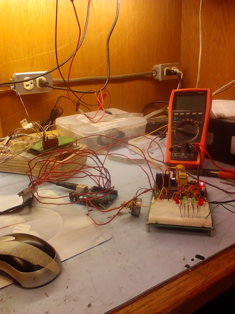
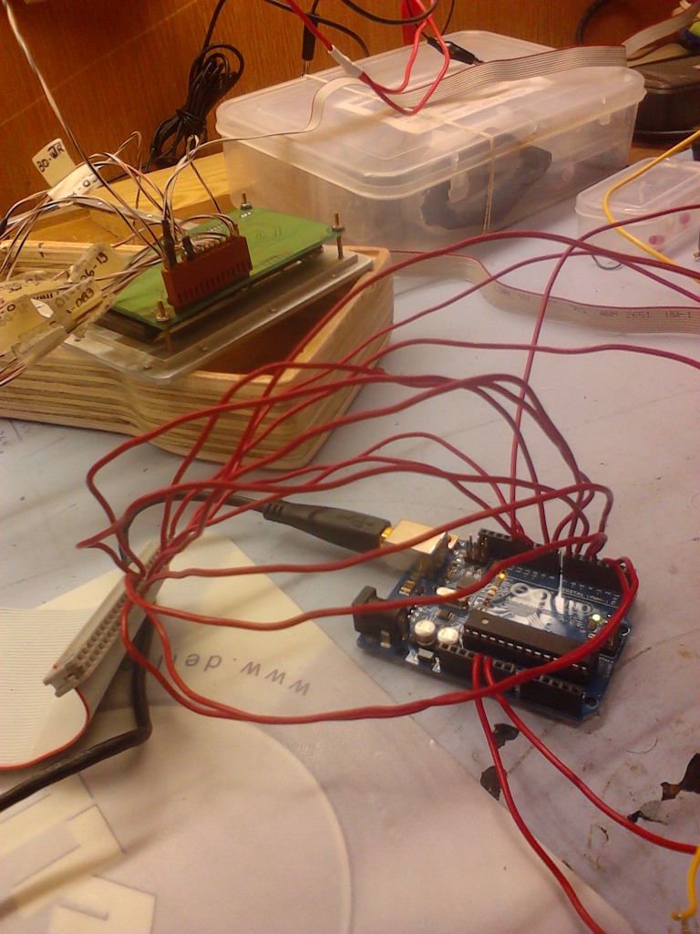
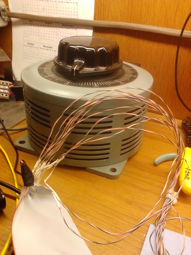
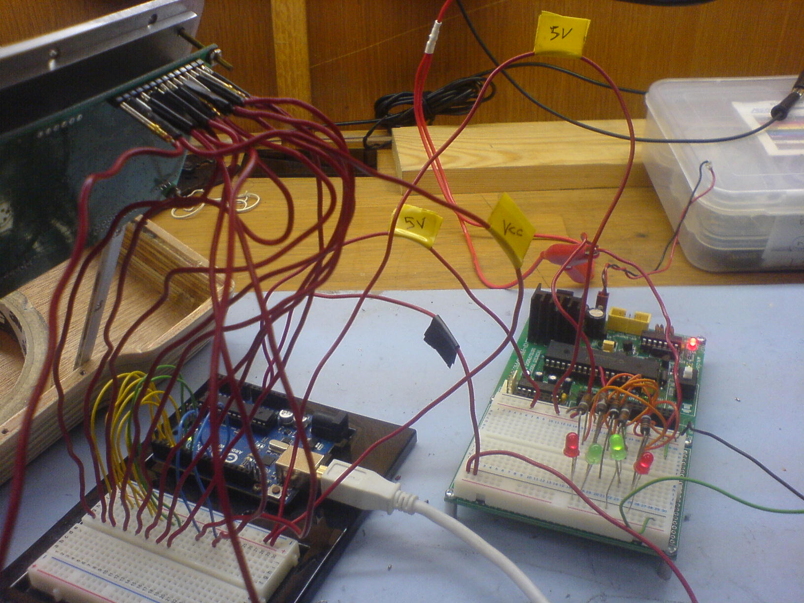
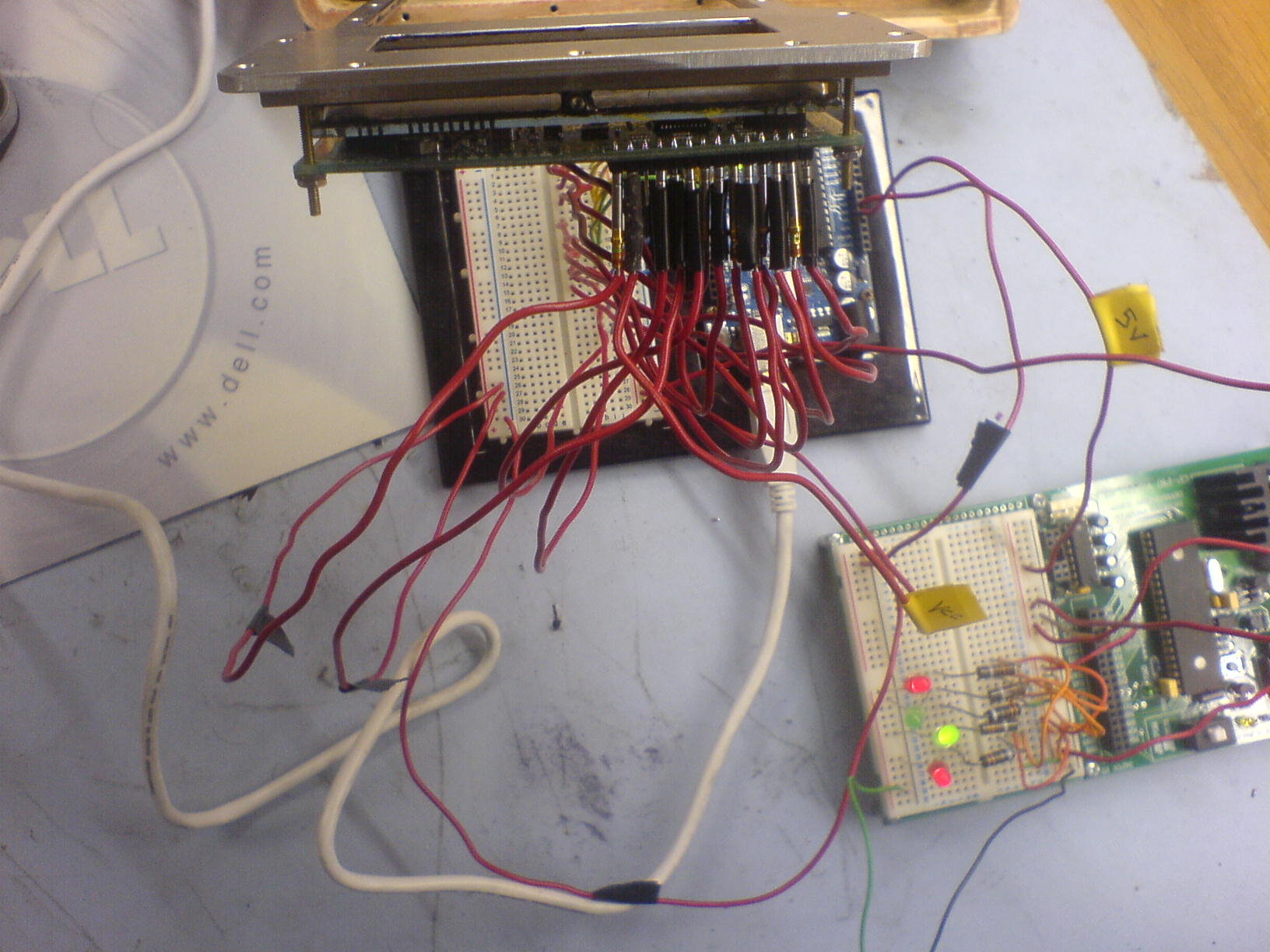
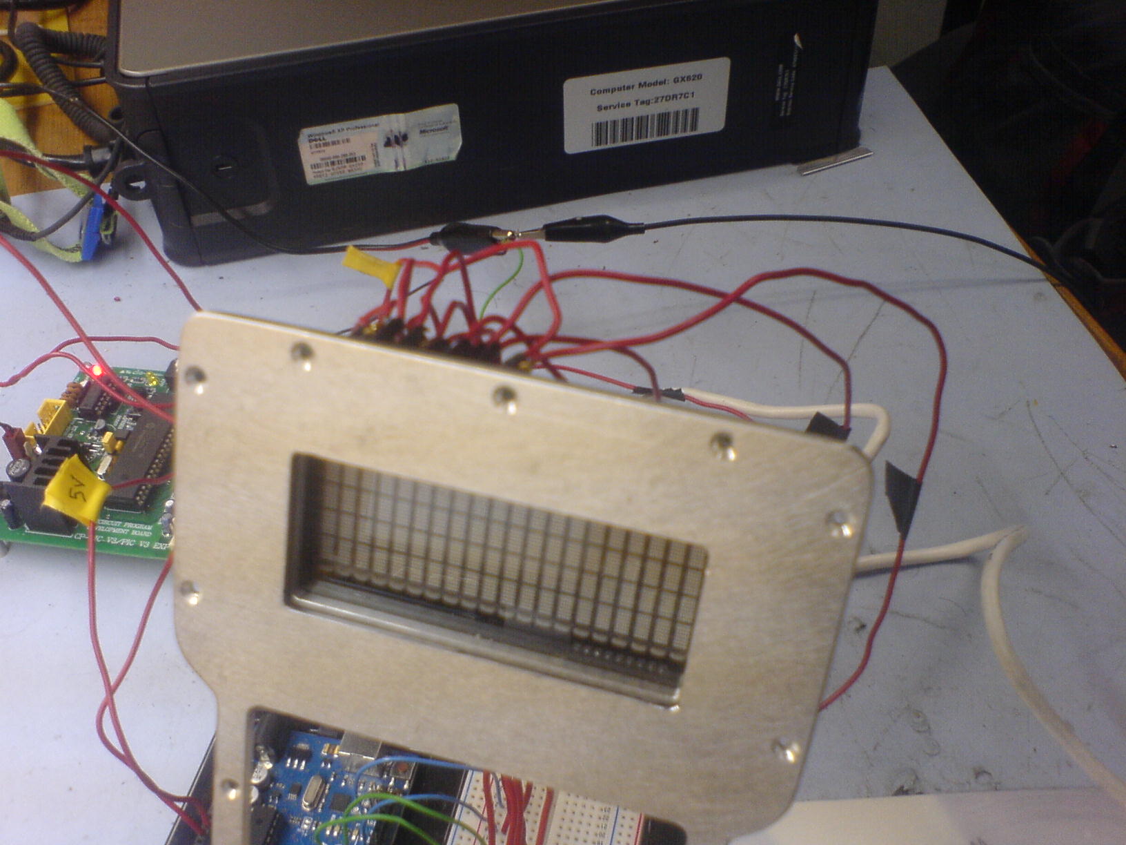
These are pictures of the actual apparatus being used. The pins emanating from behind the vfd are connected via red jumpers to the arduino breadboard and then to the arduino via yellow and green lines for data and blue wires for EN and RS . The display was given to me in this metal framework, and was instructed to leave it there. The PIC board was what I attempted to originally get the display to run on; it uses the parallel port interfacing which gave problems in terms of connectivity. I have an addtional external 5V DC power supply, the leads coming in from the bottom right of picture 1. The yellow tape on jumpers indicate 5V; the black tape, ground.
Also sent the schematic of the wiring and timing diagram extension for the unit.
Apologize for the delayed response; got your email after work hours.
Dave.
![]()
![]()
![]()
Thanks for your response.
These are pictures of the actual apparatus being used. The pins emanating from behind the vfd are connected via red jumpers to the arduino breadboard and then to the arduino via yellow and green lines for data and blue wires for EN and RS . The display was given to me in this metal framework, and was instructed to leave it there. The PIC board was what I attempted to originally get the display to run on; it uses the parallel port interfacing which gave problems in terms of connectivity. I have an addtional external 5V DC power supply, the leads coming in from the bottom right of picture 1. The yellow tape on jumpers indicate 5V; the black tape, ground.
Also sent the schematic of the wiring and timing diagram extension for the unit.
Apologize for the delayed response; got your email after work hours.
Dave.
Wed Jun 06 2012, 09:00 pm
Hey UK,
Appreciate much the advice. Actually, was thinking the same thing, that it would be a cinch, employing the LCD routine for the vfd, given the very close correspondence in terms of the timing diagrams and also the instructiions tables for both. However, it has turned out to be quite a prolonged and frustrating experience.
I have used wraps of electrical tape on the connectors to the pins at the back of the vfd and am quite certain that there is no shorting, and that there is proper connection to the pns.
The software I have used is written for the Atmega 328P and have posted; actually two versions, since I'm not quite sure how to get the delays for the program which would implement the timing diagram for the vfd according to the datasheet.
I don't have an LCD module available, but have sent for 2 of them, a 16x2 and 20x4, 5x7 dot matrix, arduino compatible.
Here's what I got.
//////////////////////////////
![]()
![]()
![]()
Appreciate much the advice. Actually, was thinking the same thing, that it would be a cinch, employing the LCD routine for the vfd, given the very close correspondence in terms of the timing diagrams and also the instructiions tables for both. However, it has turned out to be quite a prolonged and frustrating experience.
I have used wraps of electrical tape on the connectors to the pins at the back of the vfd and am quite certain that there is no shorting, and that there is proper connection to the pns.
The software I have used is written for the Atmega 328P and have posted; actually two versions, since I'm not quite sure how to get the delays for the program which would implement the timing diagram for the vfd according to the datasheet.
I don't have an LCD module available, but have sent for 2 of them, a 16x2 and 20x4, 5x7 dot matrix, arduino compatible.
Here's what I got.
// Program to operate a Vacuum Fluorescent Display
// using an Arduinno Uno, Atmega328P microcontroller.

//code: [modified eg 12.5.4-Mazidi, 8 pin 2 ports]


#define F_CPU 16000000UL

#include <avr/io.h>

#include <util/delay.h>


#define	LCD_DPRT  PORTD	        // configuring PortD for data
#define	LCD_DDDR  DDRD
#define	LCD_DPIN  PIND
#define	LCD_CPRT  PORTB         // utilizing PortB pins for the control.
#define	LCD_CDDR  DDRB
#define	LCD_CPIN  PINB
#define	LCD_RS  0 		// control pin assignments.
#define	LCD_RW  1
#define	LCD_EN  2

//*******************************************************
void delay_us(unsigned int d)
{
  _delay_us(d);
}

//*******************************************************
void lcdCommand( unsigned char cmnd )
{
  LCD_DPRT = cmnd;	       // ready data lines
  LCD_CPRT &= ~ (1<<LCD_RS);   // RS low (lower line on the timing diagram)to select the Instruction register.
  LCD_CPRT &= ~ (1<<LCD_RW);   // RW low to write instructions.
  LCD_CPRT |= (1<<LCD_EN);     // Enable pin high to latch data on the falling edge.
  delay_us(.23);	       // Enable pin high for 230 ns to enable latching of instruction set.
  LCD_CPRT &= ~ (1<<LCD_EN);   // LCD_EN pin of PortB low after sending an instruction.
  delay_us(.23);	       // Delay 230 ns between instructions sent.
}

//*******************************************************
void lcdData( unsigned char data )
{
  LCD_DPRT = data;
  LCD_CPRT |= (1<<LCD_RS);     // RS pin high (upper line on the timing diagram)to select the Data register.
  LCD_CPRT &= ~ (1<<LCD_RW);   // RW low to write instructions.
  LCD_CPRT |= (1<<LCD_EN);     // Enable pin set to latch data on the falling edge.
  delay_us(.23);               // Enable pin high for 230 ns to enable latching of data set.
  LCD_CPRT &= ~ (1<<LCD_EN);   // LCD_EN pin of PortB low after sending data byte.
  delay_us(.23);	       // Delay 230 ns between instructions sent.
}

//*******************************************************
void lcd_init()                // Equivalent to void InitializeComputerBoard (void).
{                              // ...exception: the delay btwn clear display and entry mode.
  LCD_DDDR = 0xFF;             // Port D is configured as output.
  LCD_CDDR = 0xFF;             // Port B is configured as output.

  LCD_CPRT &=~(1<<LCD_EN);     // LCD_EN pin of PortB is cleared in preparation for sending commands.
  delay_us(2000);	       // delay of 2ms before sending commands.
  lcdCommand(0x38);	       // Function set command.
  lcdCommand(0x0E);	       // Display on with blinking cursor.
  lcdCommand(0x01);	       // Display cleared.
  delay_us(2000);
  lcdCommand(0x06);	       // Entry mode set
}

//*******************************************************
void lcd_gotoxy(unsigned char x, unsigned char y)
{
 unsigned char firstCharAdr[]={0x80,0xC0,0x94,0xD4};    //table 12-5 of text.
 lcdCommand(firstCharAdr[y-1] + x - 1);      // calculating the address location to the first and subsequent characters.
 delay_us(100);	              // delay of 100us btwn each character being displayed
}

//*******************************************************
void lcd_print( char * str )
{
  unsigned char i = 0 ;
  while(str[i]!=0)
  {
    lcdData(str[i]);         // string array of characters to be displayed
    i++ ;                    // each member of array called up incrementally.
  }
}

//*******************************************************
int main(void)
{
  lcd_init();               // init routine.
  lcd_gotoxy(1,1);
  lcd_print("The world is but");
  lcd_gotoxy(1,2);
  lcd_print("one country");
  while(1);		    // do forever.
  return 0;
}
//////////////////////////////
// (same as above except busy routine replaces second delay.
#define	LCD_DPRT  PORTD	        // configuring PortD for data
#define	LCD_DDDR  DDRD
#define	LCD_DPIN  PIND
#define	LCD_CPRT  PORTB         // utilizing PortB pins for the control.
#define	LCD_CDDR  DDRB
#define	LCD_CPIN  PINB
#define	LCD_RS  0 		// control pin assignments.
#define	LCD_RW  1
#define	LCD_EN  2
#define LCD_D7  3
//*******************************************************
void delay_us(unsigned int d)
{
  _delay_us(d);
}
//*******************************************************
void LCD_busy()
{
     DDRD = DDRD &= ~ (1<<LCD_D7); //Make D7th bit of LCD as input
     DDRB = DDRB |= (1<<LCD_EN);   //Make port pin as output
     LCD_CPRT &= ~ (1<<LCD_RS);    //Selected instruction register
     LCD_CPRT   |= (1<<LCD_RW);    //We are reading
     while(LCD_D7){                //read busy flag again and again till it becomes 0
       LCD_CPRT &= ~ (1<<LCD_EN);  //Enable H->
L
       LCD_CPRT |= (1<<LCD_EN);
     }
}
//*******************************************************
void lcdCommand( unsigned char cmnd )
{
  LCD_DPRT = cmnd;	       // ready data lines
  LCD_CPRT &= ~ (1<<LCD_RS);   // RS low (lower line on the timing diagram)to select the Instruction register.
  LCD_CPRT &= ~ (1<<LCD_RW);   // RW low to write instructions.
  LCD_CPRT |= (1<<LCD_EN);     // Enable pin high to latch data on the falling edge.
  delay_us(.23);	       // Enable pin high for 230 ns to enable latching of instruction set.
  LCD_CPRT &= ~ (1<<LCD_EN);   // LCD_EN pin of PortB low after sending an instruction.
  LCD_busy();                  // Wait for LCD to process the command.
}

//*******************************************************
void lcdData( unsigned char data )
{
  LCD_DPRT = data;
  LCD_CPRT |= (1<<LCD_RS);     // RS pin high (upper line on the timing diagram)to select the Data register.
  LCD_CPRT &= ~ (1<<LCD_RW);   // RW low to write instructions.
  LCD_CPRT |= (1<<LCD_EN);     // Enable pin set to latch data on the falling edge.
  delay_us(.23);               // Enable pin high for 230 ns to enable latching of data set.
  LCD_CPRT &= ~ (1<<LCD_EN);   // LCD_EN pin of PortB low after sending data byte.
  LCD_busy();                  // Wait for LCD to process the command.
}


Powered by e107 Forum System

Tumergix
Sun Apr 28 2024, 12:59 am

StevenDrulk
Sat Apr 27 2024, 08:47 pm

StephenHauct
Sat Apr 27 2024, 09:38 am

Adamsaf
Sat Apr 27 2024, 07:12 am

Robertphype
Sat Apr 27 2024, 12:23 am

ktaletrryp
Fri Apr 26 2024, 10:55 pm

Robertrip
Fri Apr 26 2024, 11:20 am

ArnoldDiant
Fri Apr 26 2024, 03:53 am