avr to vfd


Thu Jun 07 2012, 02:29 am
Dont stick to the timings so much. coz if you look at the datasheet they mentioned only the minimum timings that are needed. so they are not critical at all.
The only thing I feel the problem is.. you are putting way too much delay than I thought. I just missed it somehow in the older posts. I just had a look at it. you are calling delay us as
delay_us(.23); ---> 0.23? decimal value and delay_us is expecting an integer so acutally you're passing 0 to the function. change it to 1 instead of 0.23
Second MAJOR problem is the busy function loop...
while(LCD_D7) ?????
LCD_D7 is defined as 3 so your loop is always true and you are stuck for ever in the loop. change it to
give it one more try hope it works this time
The only thing I feel the problem is.. you are putting way too much delay than I thought. I just missed it somehow in the older posts. I just had a look at it. you are calling delay us as
delay_us(.23); ---> 0.23? decimal value and delay_us is expecting an integer so acutally you're passing 0 to the function. change it to 1 instead of 0.23
Second MAJOR problem is the busy function loop...
 while(LCD_D7){                //read busy flag again and again till it becomes 0
       LCD_CPRT &= ~ (1<<LCD_EN);  //Enable H->
L
       LCD_CPRT |= (1<<LCD_EN);
     }
while(LCD_D7) ?????
LCD_D7 is defined as 3 so your loop is always true and you are stuck for ever in the loop. change it to
while(LCD_DPRT & (1 << LCD_D7))
give it one more try hope it works this time
[ Edited Thu Jun 07 2012, 02:29 am ]


Fri Jun 08 2012, 04:01 am
Ajay,
Appreciate your response and suggestion.Thanks for pointing that out, the integral value called out by the delay function. I take it this is irrespective of the fact that the timihg diagram indicates fractions of a microsecond in which case it is interesting how the compiler didnt indicate a type mismatch when it compiled with the fractional value. Anyhow, hammering away at this thing, I changed the data type and put it in that tweak you suggested. I also remember from my experience in putting together the code for the PIC that in the busy routine after you make 7th bit for input to detect busy signal, you then afterward make it as an output to resend data (hope I have phrased this correctly) and so i included that last line in the busy routine.
Also, I know it may be a bit to look at but as mentioned have been on the arduino site with another gentleman who has been gracious enough to also help solve this problem. I add the script of our correspondence and was wondering if you could critique the steps we have taken and the progress made thus far, and if you think it might lead to a breakthough of sorts.
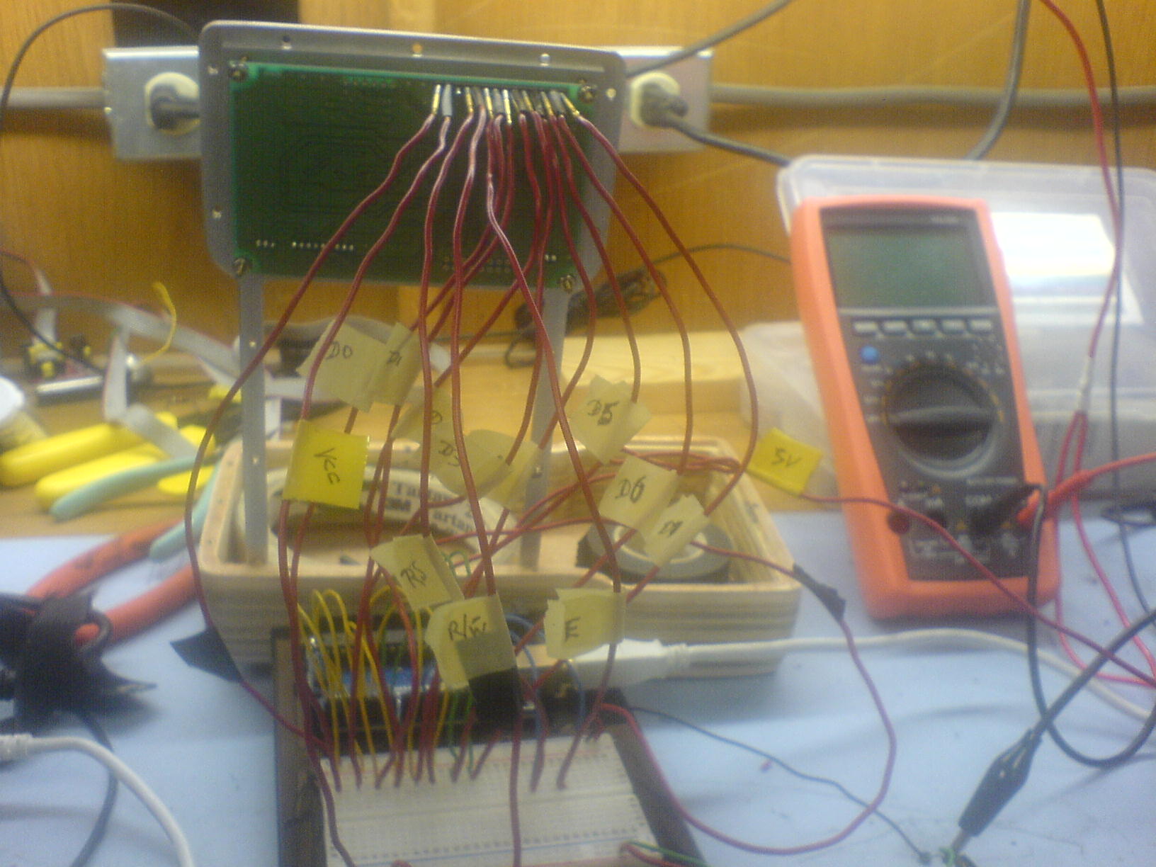
I've also recrimped new pin insertions for and labelled the jumpers to make it more presentable.
Oh, one other thing,don't know if I mentioned it, but before when I had the CIODIO48 ribbon as interconnection between the uno and the display never got that 'avrdude: stk500_getsync(): not in sync: resp=0x00'. Now I have to unhook the connection to the Rx pin, to upload a program and then put it back into position; do you suppose that could be a factor in this thing not coming to life?
Anyhow, this is what I got....and still midnight. I also add the timing diagram vfd-lcd comparison for quick referrence: OK!!!! I take that back! The BUSY LCD code compiles without the an issue, all pins connected to the arduino....just hitting a shot before I leave work here!? Weird....but still nothing.
![]()
Appreciate your response and suggestion.Thanks for pointing that out, the integral value called out by the delay function. I take it this is irrespective of the fact that the timihg diagram indicates fractions of a microsecond in which case it is interesting how the compiler didnt indicate a type mismatch when it compiled with the fractional value. Anyhow, hammering away at this thing, I changed the data type and put it in that tweak you suggested. I also remember from my experience in putting together the code for the PIC that in the busy routine after you make 7th bit for input to detect busy signal, you then afterward make it as an output to resend data (hope I have phrased this correctly) and so i included that last line in the busy routine.
Also, I know it may be a bit to look at but as mentioned have been on the arduino site with another gentleman who has been gracious enough to also help solve this problem. I add the script of our correspondence and was wondering if you could critique the steps we have taken and the progress made thus far, and if you think it might lead to a breakthough of sorts.
I've also recrimped new pin insertions for and labelled the jumpers to make it more presentable.
Oh, one other thing,don't know if I mentioned it, but before when I had the CIODIO48 ribbon as interconnection between the uno and the display never got that 'avrdude: stk500_getsync(): not in sync: resp=0x00'. Now I have to unhook the connection to the Rx pin, to upload a program and then put it back into position; do you suppose that could be a factor in this thing not coming to life?
Anyhow, this is what I got....and still midnight. I also add the timing diagram vfd-lcd comparison for quick referrence: OK!!!! I take that back! The BUSY LCD code compiles without the an issue, all pins connected to the arduino....just hitting a shot before I leave work here!? Weird....but still nothing.
#define LCD_D7  3
//*******************************************************
void delay_us(float d)
{
  _delay_us(d);
}
//*******************************************************
void LCD_busy()
{
     DDRD = DDRD &= ~ (1<<LCD_D7); //Make D7th bit of VFD as input.
     DDRB = DDRB |= (1<<LCD_EN);   //Make port pin as output
     LCD_CPRT &= ~ (1<<LCD_RS);    //Selected instruction register
     LCD_CPRT   |= (1<<LCD_RW);    //We are reading
     while(LCD_D7 & (1 << LCD_D7)) //read busy flag again and again till it becomes 0
      {
        LCD_CPRT &= ~ (1<<LCD_EN); //Enable H->
L
        LCD_CPRT |= (1<<LCD_EN);
      }
     DDRD = DDRD |= (1<<LCD_D7);   // Make D7th bit of VFD as output.
}
//*******************************************************
void lcdCommand( unsigned char cmnd )
{
  LCD_DPRT = cmnd;	       // ready data lines
  LCD_CPRT &= ~ (1<<LCD_RS);   // RS low (lower line on the timing diagram)to select the Instruction register.
  LCD_CPRT &= ~ (1<<LCD_RW);   // RW low to write instructions.
  delay_us(.020);              // Delay 20 ns for address set-up time.
  LCD_CPRT |= (1<<LCD_EN);     // Enable pin high to latch data on the falling edge.
  delay_us(.23);	       // Enable pin high for 230 ns to enable latching of instruction set.
  LCD_CPRT &= ~ (1<<LCD_EN);   // LCD_EN pin of PortB low after sending an instruction.
  LCD_busy();                  // Wait for LCD to process the command.
}

//*******************************************************
void lcdData( unsigned char data )
{
  LCD_DPRT = data;
  LCD_CPRT |= (1<<LCD_RS);     // RS pin high (upper line on the timing diagram)to select the Data register.
  LCD_CPRT &= ~ (1<<LCD_RW);   // RW low to write instructions.
  delay_us(.020);              // Delay 20 ns for address set-up time.
  LCD_CPRT |= (1<<LCD_EN);     // Enable pin set to latch data on the falling edge.
  delay_us(.23);               // Enable pin high for 230 ns to enable latching of data set.
  LCD_CPRT &= ~ (1<<LCD_EN);   // LCD_EN pin of PortB low after sending data byte.
  LCD_busy();                  // Wait for LCD to process the command.
}

//*******************************************************
void lcd_init()                // Equivalent to void InitializeComputerBoard (void).
{                              // ...exception: the delay btwn clear display and entry mode.
  LCD_DDDR = 0xFF;             // Port D is configured as output.
  LCD_CDDR = 0xFF;             // Port B is configured as output.

  LCD_CPRT &=~(1<<LCD_EN);     // LCD_EN pin of PortB is cleared in preparation for sending commands.
  delay_us(.666);	       // Delay of 666ns before sending commands.
  lcdCommand(0x38);	       // Function set command.
  lcdCommand(0x0E);	       // Display on with blinking cursor.
  lcdCommand(0x01);	       // Display cleared.
  delay_us(.666);	       // Delay of 666ns between instruction sets.
  lcdCommand(0x06);	       // Entry mode set
}

Fri Jun 08 2012, 06:25 am
Messy wiring can work, but usually it lets you down.
I think it is time to start again.
Rewire your display.
No wires pushed into connections,no breadboard, solder to proper connecting pins.
Post your circuit diagram as well.
I think it is time to start again.
Rewire your display.
No wires pushed into connections,no breadboard, solder to proper connecting pins.
Post your circuit diagram as well.
[ Edited Fri Jun 08 2012, 06:26 am ]
dvlee like this.
Fri Jun 08 2012, 08:32 am
Believe you me i'm all for esthetics and precision and desired results as well. As mentioned, was not allowed to remove the display from the framework, but to work it with initially the ribbon which was attached to a ciodio48 pcb within a computer, and then by itself. So I've tried as best I could to work connectors at the end of jumpers onto the protuding pins of the display. I can perhaps cut the jumpers to exact lengths and work then onto the breadboard as I attempted to do.
If you have pictorial egs that you know of, or a site that I can go to for egs, given the constraint I have to work with, I'm more than open to suggestions. Appreciate the comments.
D.
If you have pictorial egs that you know of, or a site that I can go to for egs, given the constraint I have to work with, I'm more than open to suggestions. Appreciate the comments.
D.
Fri Jun 08 2012, 08:52 am
Additiionally, I'm quite certain that the connections from the pins at the back of the display are very good. To that effect I recrimped new very fitted connectors at the ends of the red jumpers that fit snugly onto the pins and dont come off easily. I've made sure of proper insertions into and breadboard and arduino, and no strain on the wires that may cause dislodging. I'm very tempted to take the display off and do the soldering to the uno directly via jumpers, but trying to avoid the ire of the super.
Oh, another thing, the circuit diagram is essentially the connections as shown in the schematic posted here.
Oh, another thing, the circuit diagram is essentially the connections as shown in the schematic posted here.
Sat Jun 09 2012, 04:33 pm
do you know the argument datatype for _delay_us function?? I dont know why are you so obsessed with timing. I already mentioned that timings is not an issue here. just make sure you keep timing more than what is mentioned there. e.g. 230ns is mentioned then keep 1ms safe side.. 660ns is mentioned keep 2ms there.
I think you better take scope and see if your signals are coming proper or not, also make use of general 20x2 or 16x2 LCD and try out your code. both VFD and normal LCD are similar. so if your code works on normal LCD then it should work on VFD too. So you can left with only one issue that is hardware.
I think you better take scope and see if your signals are coming proper or not, also make use of general 20x2 or 16x2 LCD and try out your code. both VFD and normal LCD are similar. so if your code works on normal LCD then it should work on VFD too. So you can left with only one issue that is hardware.
dvlee like this.
Tue Oct 16 2012, 09:03 am
Hello again Ajay.
It has been a while since I've been on this simple project, so much so that I have not given up and not forgotten about it and have decided to incorporate into my senior design for graduation next two months. I've done quite a bit of research and learned a lot from this forum and others as well and really want to get this display to work as for the handheld would like to produce.
Anyhow, since the last we communicated, I have connected 16x2 LCDs to a ruggeduino and 2560 and ran arduino sketches that have given me the text displays I've encoded.The LCDs display messages for the set sketch examples from the arduino IDE, in 4 bit mode, and I'm trying to get it to work in 8bit mode. The program I've come up with in 8 bit mode compiles, but when uploaded, just clears the LCDs showing only the top row of pixels. I'm eventually wanting to tweek this program to run the Noritake itron CW20045-UW5A vacuum fluorescent display whose timing diagram is somewhat different, and the program would have to be altered in terms of the delay time for the enable pin to latch the instruction and data sets, as well as the address set-up time.The code I have is presented below. I remember what you said, dont make a meal of the timing and so I wont, but whatever it takes to get this thing to work, and i know it works, I'll do.
Here's what I have in terms of coding:
Powered by e107 Forum System

KevinTab
Sun Apr 28 2024, 05:35 am

Tumergix
Sun Apr 28 2024, 12:59 am

StevenDrulk
Sat Apr 27 2024, 08:47 pm

StephenHauct
Sat Apr 27 2024, 09:38 am

Adamsaf
Sat Apr 27 2024, 07:12 am

Robertphype
Sat Apr 27 2024, 12:23 am

ktaletrryp
Fri Apr 26 2024, 10:55 pm

Robertrip
Fri Apr 26 2024, 11:20 am