Bluetooth heart rate monitor?


Actually would anyone recommend a particular type of bluetooth adapter to go with the AT89S52 or are they all kinda the samePeter_Parker
The HC04,05 ,06,07 should be okay.
HC05/07 is a master /slave while the HC04/06 are slave only,but slave is what you want
Note.. There can be minor difference in the same model, dependent on the
software version, so check any code samples that come with it.


mostly bluetooth modules are same. All you need to look for is SPP support.
Any progress on the sensor side?Ajay Bhargav
I'm still waiting on a ultra bright led and a capacitor I ordered to come before I start testing it,the rest is built on a breadboard.
Most bluetooth modules I've looked at seem to be a 3.3v input although my circuit is running off a 9v battery(regulated down to 5v)
The HC-05/HC-06 module seems popular with 8051 circuits.
Although I'm a little lost at the importance of the 3.3v logic level feeding back to the mcu along the transmit and recieve lines

on rx side I think its fine if you connect it directly. 3.3v should lie in the Voh range (output high voltage). On tx side, you can either use a voltage divider or a level shifter SN74LVC series.Ajay Bhargav
Ya I finding it awkward to find info on the HC-06 when connecting it to 5volt devices but I did see some info on a EGBT-046S module about protecting the inputs

Is this along the lines of what you mean?
http://www.8051projects.net/download-d247-android-controlled-robot-using-8051-microcontroller.html
I am sure you will get some help from its schematic while designing your circuit. as 8051 is working on 5V and HC05 is 3.3v.
Yes EGBT-046S mentions the same thing that I was referring to. Anyways, HC-05 module is used in this project:
http://www.8051projects.net/download-d247-android-controlled-robot-using-8051-microcontroller.html
I am sure you will get some help from its schematic while designing your circuit. as 8051 is working on 5V and HC05 is 3.3v.Ajay Bhargav
Thanks I will look through that project although these might be two alternative solutions
Solution 1:
Reading on in EGBT manual there's a diagram provided on connecting to 5v microcontrollers

Solution 2:
Another I read was
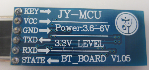
"Some boards have VCC labeled for working voltages up to ~6 volts. These modules DO NOT like anything except 3.3 volts on the VCC line. Also, some forums claim that the device works fine with 5 volt TTL levels. This is also not true and you should use a level converter to 3.3V on the RXD line. I used two resistors as a simple voltage divider to make the TTL level conversion. One 2.2k ohm resistor to ground, connected to a 1k ohm resistor, to the TXD line on the MCU. Connect the RXD pin in between the two resistors for an output of approx 3.4 volts."

http://www.instructables.com/id/Success-Using-the-JY-MCU-linvor-Bluetooth-Module/
[ Edited Wed Mar 12 2014, 05:44 am ]
You can also use a series diode (usually have forward voltage drop of 0.5-0.7v) so like using two diodes in series will give you max 1.4V so 5-1.4 = 3.6v but still resistor divider is better

Well both solutions are good. It depends on you which one you want to choose. Voltage divider and using a level shifter IC is what I already mentioned. But using special IC will increase cost so a voltage divider using resistor circuit (solution 2) is one of the cheapest solution.
You can also use a series diode (usually have forward voltage drop of 0.5-0.7v) so like using two diodes in series will give you max 1.4V so 5-1.4 = 3.6v but still resistor divider is betterAjay Bhargav
Ya as I did a bit more searching and solution two seems to be a popular option

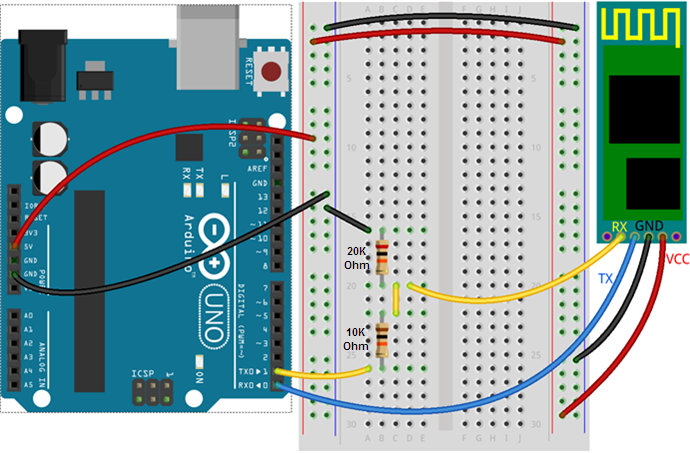
http://42bots.com/tutorials/how-to-connect-arduino-uno-to-android-phone-via-bluetooth/
And I think I can use any resistors values once I follow the voltage divider equation
waiting for update. I've seen a few different codes,some here,some on different sites,all look similar enough but thought I'd start with one I saw here
#include reg51.h
//#include
void _nop_(void);
#define delay_us _nop_(); //generates 1 microsecond
#define LCD P3
sbit RS=P2^0; //connect p0.0 to rs pin of lcd
sbit EN=P2^2; //connect p0.1 to en pin of lcd
sbit RW=P2^1;
sbit PULSE=P0^0; //pulse input from heart beat sensor
//sbit LED=P1^0; //led indicator for pulse indication
void integer_lcd(int);
void init_lcd(void);
void cmd_lcd(unsigned char);
void write_lcd(unsigned char);
void delay_ms(unsigned int);
unsigned int num=0;
unsigned int num1=0;
unsigned int dig_1,dig_2,dig_3,dig_4,test=0;
unsigned int dig_11,dig_21,dig_31,dig_41,test1=0,test2=0;
unsigned char k=0;
void main(void)
{
init_lcd();
//LED=0;
write_lcd('H');
write_lcd('E');
write_lcd('A');
write_lcd('R');
write_lcd('T');
write_lcd(' ');
write_lcd('B');
write_lcd('E');
write_lcd('A');
write_lcd('T');
write_lcd(' ');
write_lcd(' ');
write_lcd(' ');
write_lcd(' ');
write_lcd(' ');
write_lcd(' ');
cmd_lcd(0xc0);
write_lcd(' ');
write_lcd(' ');
write_lcd(' ');
write_lcd(' ');
write_lcd(' ');
write_lcd(' ');
write_lcd(' ');
write_lcd(' ');
write_lcd('C');
write_lcd('O');
write_lcd('U');
write_lcd('N');
write_lcd('T');
write_lcd('E');
write_lcd('R');
delay_ms(300);
cmd_lcd(0x01);
write_lcd('B');
write_lcd('e');
write_lcd('a');
write_lcd('t');
write_lcd('s');
write_lcd(':');
write_lcd(48);
write_lcd(48);
write_lcd(48);
write_lcd(48);
	while(1)
	{
	if(PULSE==1) //check for input pulse from sensor
 {
cmd_lcd(0x01);
test++;
num=test;
dig_4=num%10;
num=num/10;
dig_3=num%10;
num=num/10;
dig_2=num%10;
dig_1=num/10;
	 if(test==9999)
test=0;
write_lcd('B');
write_lcd('e');
write_lcd('a');
write_lcd('t');
write_lcd('s');
write_lcd(':');
write_lcd(dig_1+48);
write_lcd(dig_2+48);
write_lcd(dig_3+48);
write_lcd(dig_4+48);
//LED=1;
delay_ms(50);
//LED=0;
 }
	}
	}
////////////////////////////////////////////////////////////////
void init_lcd(void)
{
delay_ms(10); //delay 10 milliseconds
cmd_lcd(0x38); //8 bit initialize, 5x7 character font, 16x2 display
cmd_lcd(0x0e); //lcd on, cursor on
cmd_lcd(0x06); //right shift cursor automatically after each character is displayed
cmd_lcd(0x01); //clear lcd
}
//transmit command or instruction to lcd
void cmd_lcd(unsigned char c)
{
EN=1;
RW=0;//set enable pin
RS=0; //clear register select pin
LCD=c; //load 8 bit data
EN=0; //clear enable pin
delay_ms(2); //delay 2 milliseconds
}
//transmit a character to be displayed on lcd
void write_lcd(unsigned char c)
{
EN=1; //set enable pin
RW=0;
RS=1; //set register select pin
LCD=c; //load 8 bit data
EN=0; //clear enable pin
delay_ms(2); //delay 2 milliseconds
}
//generates delay in milli seconds
void delay_ms(unsigned int i)
{
unsigned int j;
	while(i-->
0)
	{
	 for(j=0;j<500;j++)
	 {
	 ;
	 }
	}
}
I think this only works as a pulse counter so to calculate the beats per minute a time reference is needed I think.
When I load it onto my chip,the welcome message comes up on the lcd and then everytime I put my finger on the lrd the no of beats increment by 1 on the lcd screen.
[ Edited Sat Apr 05 2014, 10:02 pm ]


