ADC0804 Interfacing with AVR Microcontroller From Rikipedia Embedded Wiki
ADC0804 Pin-out and Typical Connections
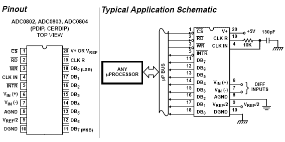
As shown in the typical circuit, ADC0804 can be interfaced with any microcontroller. You need a minimum of 11 pins to interface ADC0804, eight for data pins and 3 for control pins. As shown in the typical circuit the chip select pin can be made low if you are not using the microcontroller port for any other peripheral (multiplexing).

ADC0804 Pin Diagram
There is a universal rule to find out how to use an IC. All you need is the datasheet of the IC you are working with and take a look at the timing diagram of the IC which shows how to send the data, which signal to assert and at what time the signal should be made high or low etc.
Note: Keep this in mind that whenever you are working with an IC and you want to know how to communicate with that IC, then simply look into the timing diagram of that IC from its datasheet. It gives you complete information that you need regarding the communication of IC.

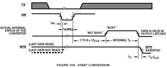
Start Conversion Timing Diagram

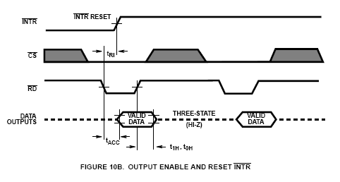
End of Conversion Timing Diagram
The above timing diagrams are from ADC0804 datasheet. The first diagram (FIGURE 10A) shows how to start a conversion. Also you can see which signals are to be asserted and at what time to start a conversion. So looking into the timing diagram FIGURE 10A. We note down the steps or say the order in which signals are to be asserted to start a conversion of ADC. As we have decided to make Chip select pin as low so we need not to bother about the CS signal in the timing diagram. Below steps are for starting an ADC conversion. I am also including CS signal to give you a clear picture. While programming we will not use this signal.
- Make chip select (CS) signal low.
- Make write (WR) signal low.
- Make chip select (CS) high.
- Wait for INTR pin to go low (means conversion ends).
Once the conversion in ADC is done, the data is available in the output latch of the ADC. Looking at the FIGURE 10B which shows the timing diagram of how to read the converted value from the output latch of the ADC. Data of the new conversion is only avalable for reading after ADC0804 made INTR pin low or say when the conversion is over. Below are the stepts to read output from the ADC0804.
- Make chip select (CS) pin low.
- Make read (RD) signal low.
- Read the data from port where ADC is connected.
- Make read (RD) signal high.
- Make chip select (CS) high.
AVR Assembly Program for ADC0804
.include "8515def.inc"

.equ rd = PORTB0           ;Read signal PortB.0
.equ wr = PORTB1           ;Write Signal PortB.1
.equ cs = PORTB2           ;Chip Select PortB.2
.equ intr = PORTB3         ;INTR signal PortB.3
.equ adc_port = PINA       ;ADC data pins PortA
.def adc_val = r16         ;To store ADC value
.def temp = r17            ;Temporary register

.org 0x00
start:
	ldi temp,low(RAMEND)   ;Load stack with
	out SPL,temp           ;RAMEND - highest value
	ldi temp,high(RAMEND)  ;of internal SRAM
	out SPH,temp

	sbi DDRB,rd            ;Make RD as o/p
	sbi DDRB,wr            ;Make WR as o/p
	sbi DDRB,cs            ;Make CS as o/p
again:
	rcall conv             ;Start ADC Conversion
	rcall read             ;Read ADC conversion
	ldi temp,0xFF
	out DDRC,temp          ;Make PORTC as o/p Port
	out PORTC,adc_val      ;Move the read value to PORT C
	rjmp again             ;Do it again

conv:                      ;Start conversion
	cbi PORTB,cs           ;Make CS low
	cbi PORTB,wr           ;Make WR low
	nop
	sbi PORTB,wr           ;Make WR high
	sbi PORTB,cs           ;Make CS high
wait:
	sbic PINB,intr         ;Wait for INTR signal
	rjmp wait

	ret                    ;Conversion done

read:                      ;Read ADC
	cbi PORTB,cs           ;Make CS low
	cbi PORTB,rd           ;Make RD low

	in adc_val,adc_port    ;Read ADC data

	sbi PORTB,rd           ;Make RD high
	sbi PORTB,cs           ;Make CS high
	ret                    ;Reading done
AVR C program for ADC0804
#include <avr/io.h>
#define adc_port PINA                    //ADC data pins PORTA
#define rd PB0                           //Read signal PORTB0
#define wr PB1                           //Write signal PORTB1
#define cs PB2                           //Chip Select PORTB2
#define intr PB3                         //INTR signal PORTB3

void conv();                             //Start Conversion
void read();                             //Read ADC value

unsigned char adc_val;

int main(){
	DDRB = (1<<rd)|(1<<wr)|(1<<cs);      //RD, WR, CS as output
	DDRC = 0xFF;                         //PORTC as output
	PORTC = 0xFF;
	while(1){                            //Forever loop
		conv();                          //Start of conversion
		read();                          //Read converted ADC
		PORTC = adc_val;                 //Move it to PORTC
	}
	return 0;
}


void conv(){
	PORTB = PORTB & (~((1<<cs)|(1<<wr))); //Make CS and WR low
	PORTB = PORTB | ((1<<cs)|(1<<wr));    //Make CS and WR high
	while(PINB&(1<<intr));                //Wait for INTR signal
}

void read(){
	PORTB = PORTB & ( ~((1<<cs)|(1<<rd))); //Make RD and CS low
	adc_val = adc_port;                    //Read ADC port
	PORTB = PORTB | ((1<<cs)|(1<<rd));     //Make RD and CS high
}
Further Reading
- Analog to Digital Converter
- ADC0804 Interfacing with 8051 Microcontroller
- ADC0808 Interfacing Tutorial
- ADS1115 ADC Interfacing Tutorial
Help & Queries
If you have any queries, doubts or feedback on this tutorial please share in our discussion forum. If you want us to write tutorial for more devices please let us know in the forum.