Choosing of CT For the ADE7758
Discussion in "Project Help" started by SANATH EMBEDDED Jan 5, 2009.


Mon Jan 05 2009, 01:00 pm
Hi Guyz 
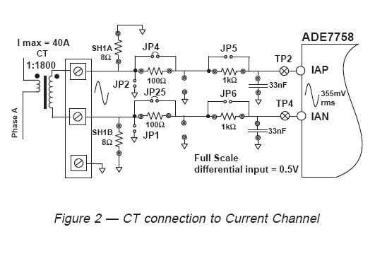
Please let me know like how the Current Transformer value can be chosen for this ADE7758 Application and what is the difference between 1:1800 CT(I max 40A) and 50:5 CT.
For reference The below ckt contains three sections for each channel 1. Burden resistor 2. RC Ckt phase Compensation 3. Anti Aliasing Low Pass Filter of corner frequency of 4.8KHz ( R=1k, C=33nF).
![]()
:bye
Please let me know like how the Current Transformer value can be chosen for this ADE7758 Application and what is the difference between 1:1800 CT(I max 40A) and 50:5 CT.
For reference The below ckt contains three sections for each channel 1. Burden resistor 2. RC Ckt phase Compensation 3. Anti Aliasing Low Pass Filter of corner frequency of 4.8KHz ( R=1k, C=33nF).
:bye
[ Edited Mon Jan 05 2009, 01:06 pm ]
sageliu like this.


Mon Jan 05 2009, 06:22 pm
do you remember in transformer electronics, we use ratio of N1/N2? ratio of primary and secondary coil? Its used for calculation of o/p current and voltage.
Mon Jan 05 2009, 08:07 pm
Thanks Ajay for the Reply :-)
CT are mainly used in AC in order to scale the larger primary currents to a smaller by stepping down it. and it depends on the ratio of number of turns. Like if we take the ratio of 50:5 CT where the o/p CT will be @ 5A when 50A current flows in the primary winding. :-)
But I didn't understand the concept of this CT of ratio 1:1800 or 1:500. Is it step Up CT ?
CT are mainly used in AC in order to scale the larger primary currents to a smaller by stepping down it. and it depends on the ratio of number of turns. Like if we take the ratio of 50:5 CT where the o/p CT will be @ 5A when 50A current flows in the primary winding. :-)
But I didn't understand the concept of this CT of ratio 1:1800 or 1:500.
Is it step Up CT ? 

Mon Jan 05 2009, 10:10 pm
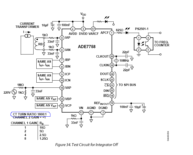
The test ckt in page 17 of the datasheet specifies a 1800:1 turns ratio.
So it's probably a typo in your schematic.
So it's probably a typo in your schematic.
Tue Jan 06 2009, 10:51 am
Thanks very much Sashijoseph :-) Rickeyworld Detective agent
Ya u r right ,The ratio is misprint, that CT ratio should be 1800:1 . I didn't much focus on the Test circuit as I was going through the Reference Evaluation board documentation where I got that above schematics given from ADE guyz.
![]()
The One more thing is like if I am making use of CT of ratio 1800:1, assuming by maximum input to the CT is 5A , so the o/p of CT will be 2.7 Milli Ampere If I am not wrong. So converting to Voltage by making use of Burden resistor value of around 50ohms , the voltage value comes around 135 milli volts which can be given to ADE7758 . since the maximum limit of differential input for ADE7758 can be given around 500 milli volts. Is this calculation is correct.
But still there is two more additional RC Ckt for phase compensation and RC Ckt Anti Aliasing Low pass filtter of corner frequency of 4.8Khz. How this will affect the input voltage given to the ADE7758
:bye
Ya u r right ,The ratio is misprint, that CT ratio should be 1800:1 . I didn't much focus on the Test circuit as I was going through the Reference Evaluation board documentation where I got that above schematics given from ADE guyz.
The One more thing is like if I am making use of CT of ratio 1800:1, assuming by maximum input to the CT is 5A , so the o/p of CT will be 2.7 Milli Ampere If I am not wrong.
So converting to Voltage by making use of Burden resistor value of around 50ohms , the voltage value comes around 135 milli volts which can be given to ADE7758 . since the maximum limit of differential input for ADE7758 can be given around 500 milli volts. Is this calculation is correct. But still there is two more additional RC Ckt for phase compensation and RC Ckt Anti Aliasing Low pass filtter of corner frequency of 4.8Khz. How this will affect the input voltage given to the ADE7758
:bye
Tue Jan 06 2009, 07:50 pm
Yes calculation is right.
regarding the RC filters, the i/p signal is limited to lower frequency because, if you see the functional block diagram, i/p singla is fed to PGA and then is given to ADC. ADC has a maximum rate of 26 KSPS. So according to Nyquist (sorry bout spelling) rate, i/p signal can only be sampled properly if its frequency is half the sampling Frequency. otherwise signal will be distorted
regarding the RC filters, the i/p signal is limited to lower frequency because, if you see the functional block diagram, i/p singla is fed to PGA and then is given to ADC. ADC has a maximum rate of 26 KSPS. So according to Nyquist (sorry bout spelling) rate, i/p signal can only be sampled properly if its frequency is half the sampling Frequency. otherwise signal will be distorted
[ Edited Tue Jan 06 2009, 07:51 pm ]
SANATH EMBEDDED like this.
Thu Jan 08 2009, 05:58 pm
Thankz very much Ajay, :-)
Even I didn't know regrading that concept You are right.
Like when continuous signal of different frequency is sampled ( not following sampling theorem) leads to aliasing or distortion. So in order to avoid that will go for Anti-aliasing low pass filter design according to the sampling theorem. In simple sampling theorem tells that " For the signal to be sampled perfectly without any aliasing regardless of architecture , the sampling frequency of ADC should be twice or more than the frequency of signal to be sampled.
So here in ADE7758 we are making use this Low pass filter as a Anti-aliasing filter of corner frequency in the range of 4.8kHz - 10khz since the sampling frequency of ADC is 26KSPS.
So the RC Low pass filter of Cut-off frequency is given by fc= 1/2(Pi)RC. So choosing the value of R=Ik and C=0.033uF , will get the cut-off frequency of 4.8KHZ.
:bye
Even I didn't know regrading that concept
You are right. Like when continuous signal of different frequency is sampled ( not following sampling theorem) leads to aliasing or distortion. So in order to avoid that will go for Anti-aliasing low pass filter design according to the sampling theorem. In simple sampling theorem tells that " For the signal to be sampled perfectly without any aliasing regardless of architecture , the sampling frequency of ADC should be twice or more than the frequency of signal to be sampled.
So here in ADE7758 we are making use this Low pass filter as a Anti-aliasing filter of corner frequency in the range of 4.8kHz - 10khz since the sampling frequency of ADC is 26KSPS.
So the RC Low pass filter of Cut-off frequency is given by fc= 1/2(Pi)RC. So choosing the value of R=Ik and C=0.033uF , will get the cut-off frequency of 4.8KHZ.
:bye
[ Edited Thu Jan 08 2009, 06:24 pm ]
Fri Jan 09 2009, 12:39 pm
Hi :-)
Even for the CT Ratio we can have something calculation like this. So input for my CT is 5A and to calculate the CT o/p, since the maximum input that can be given to ADE7758 is 0.5V , So taking up the burden resistance value R= 50ohms, according to ohms law, the current comes around 10 mA. So my CT ratio should be 5A : 10mA which comes around 500 :1. is this right
But the problem is that I have got sm old CT's along with PCB in my Trash.
Nothng is mentioned in that except sm 5/22 CT. So how can I get to know exactly what is the Ratio of that. Can I check it winding resistance using Multi-meter.
:bye
Even for the CT Ratio we can have something calculation like this. So input for my CT is 5A and to calculate the CT o/p, since the maximum input that can be given to ADE7758 is 0.5V , So taking up the burden resistance value R= 50ohms, according to ohms law, the current comes around 10 mA. So my CT ratio should be 5A : 10mA which comes around 500 :1.
is this right But the problem is that I have got sm old CT's along with PCB in my Trash.
Nothng is mentioned in that except sm 5/22 CT.
So how can I get to know exactly what is the Ratio of that. Can I check it winding resistance using Multi-meter. :bye

Fri Jan 09 2009, 11:42 pm
hi sanath,
firstly, u need to realise that the voltage sensed across the burden resistance is A.C. ( Vrms) and the max voltage input to the ADE is D.C. so while calculating the voltage and C.T. ratio, u have to see that the peak vlue does not exceed the ADE input limit.The peak value of the AC is approximately 1.414 times the r.m.s value.
To check the unknown C.T. , the D.C. resistance will not be sufficient. It also depends upon the inductance,wire gauge and no. of turns. The best way to find out is to introduce a test current to the C.T. input ( say around 1A) and check the secondary current. If u loop the same wire n times around the C.T., u will get an 'n' times multiplied output.
:-)
Sat Jan 10 2009, 10:53 am
Thaks very much PDI :-)
But at this stage I am bit confused with the following concept of AC & DC .
Okay
1. I will check out the voltage across the Burden resistance which should be AC and max input to the ADE which also will be AC since I am not making use of any rectifier ckt to convert into DC.
2. & the peak value of the AC is approximately 1.414 times the r.m.s value. Practically what does it mean.
:bye
But at this stage I am bit confused with the following concept of AC & DC .
firstly, u need to realise that the voltage sensed across the burden resistance is A.C. ( Vrms) and the max voltage input to the ADE is D.C. so while calculating the voltage and C.T. ratio, u have to see that the peak vlue does not exceed the ADE input limit.The peak value of the AC is approximately 1.414 times the r.m.s value.pdi33
Okay
1. I will check out the voltage across the Burden resistance which should be AC and max input to the ADE which also will be AC since I am not making use of any rectifier ckt to convert into DC.
2. & the peak value of the AC is approximately 1.414 times the r.m.s value. Practically what does it mean.
:bye
Powered by e107 Forum System

Clydehet
Wed May 01 2024, 06:44 pm

Davidoried
Wed May 01 2024, 06:11 pm

KevinTab
Sun Apr 28 2024, 05:35 am

Tumergix
Sun Apr 28 2024, 12:59 am

StevenDrulk
Sat Apr 27 2024, 08:47 pm

StephenHauct
Sat Apr 27 2024, 09:38 am

Adamsaf
Sat Apr 27 2024, 07:12 am

Robertphype
Sat Apr 27 2024, 12:23 am