AT89S52 AutoRange Capacitance meter


I am currently working on a project of mine which I need help with thereby I am posting this. I am building a AT89S52 microcontroller based autorange capacitance meter, I have so far interfaced it with a 16X2 LCD to print a text on the display, now I am using a LM339 comparator which is connected with a circuit that first charges and then discharges an unknown capacitor with a resistor in series. I do not know what reference voltage to set for the comparator and what sort of C code will I need to write to calculate the capacitance and display on the LCD.
Please share your thoughts and suggestions, also if you require more information please let me know.
Thanks!


the capacitor.
There are many micro controller based capacitance meters on the net,
are you basing yours on one project in particular ?
Auto-ranging will make it more complicated, I'd suggest
you make a manual version to start with.
Can you post the circuit you are using for charging/discharging
the capacitor.
There are many micro controller based capacitance meters on the net,
are you basing yours on one project in particular ?
Auto-ranging will make it more complicated, I'd suggest
you make a manual version to start with.
The attachment is the circuit I am using to carry out the charging/discharging of a capacitor across a fixed resistance in series. The potential divider with the LM339 is used to set a reference voltage of Vcc/2 i.e. 2.5V half of 5V in my case, when the voltage across the capacitor reaches this value the comparator is meant to change state and send a pulse. The problem I am having is how to write lines of code in C for this process to occur and also what code ill write to record the time for the comparator to switch states and use it to calculate the capacitance.
If you could advise me on this I would really appreciate it.
ThanksExperimenterUK
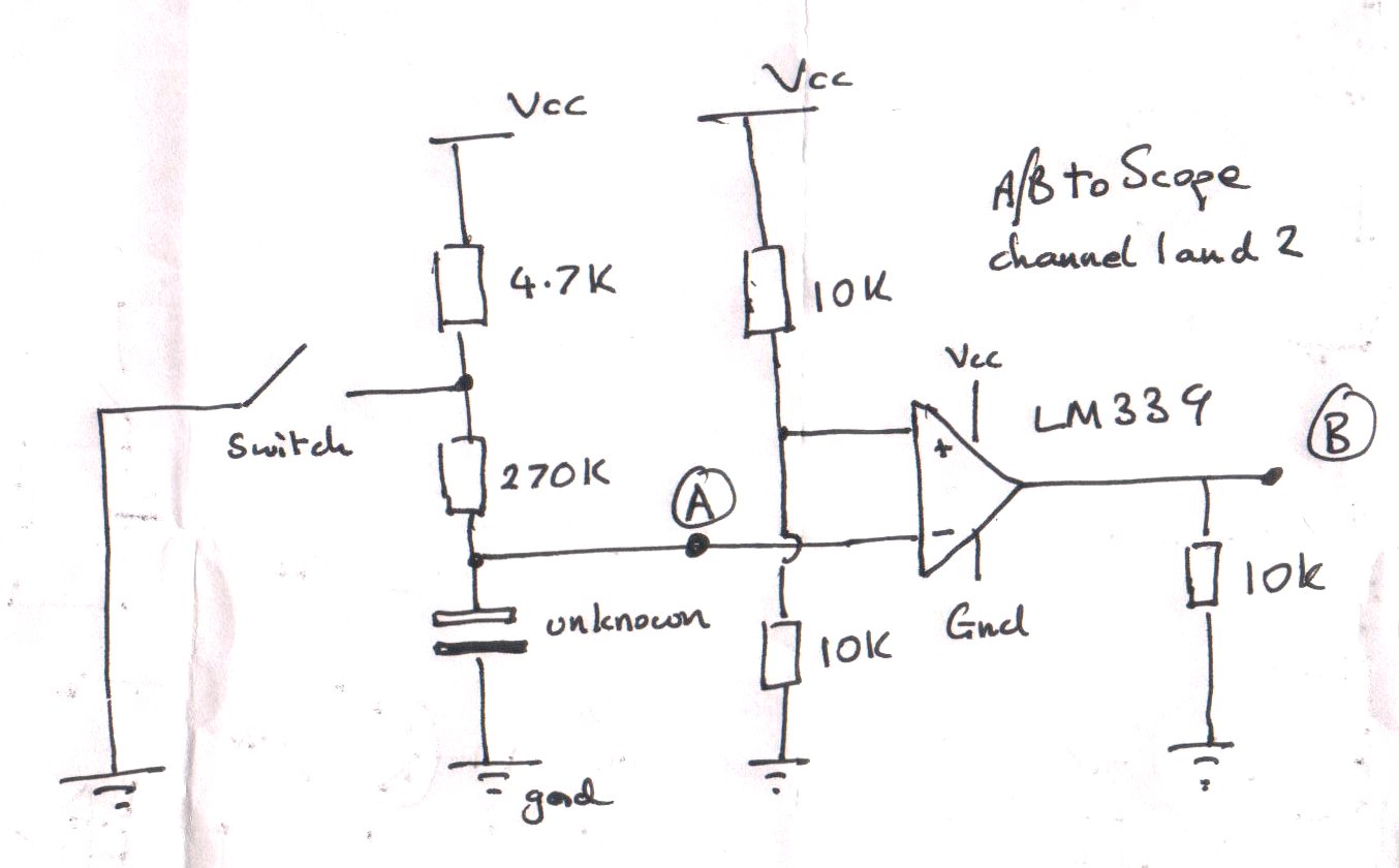
Connect your 10k resistor at 'B' to the supply voltage of the AT89S52.
For the test voltage, connect the 4.7k resistor to 12 volts.
Add a second LM339 circuit so you can detect a high and low voltage on
the capacitor.
Replace the switch with a small NPN transistor driven by an output pin of the AT89S52.
Connect a 4.7k resistor between the transistor base and the AT89S52 pin.
Connect another 4.7k resistor between the transistor and Vcc ( 5 volts).
The software will work like this.
Turn the transistor on to discharge the capacitor.
Wait until the voltage on the capacitor is below say 1/4 of
the test voltage (12 volts).
Turn the transistor off to charge the capacitor.
Wait until the voltage on the capacitor passes a 1/4 of the test voltage.
Start a counter /timer.
When the voltage passes 3/4 of the test voltage, note the count
and turn the transistor on to discharge the capacitor.
The higher the count the bigger the capacitor.
The result will not be linear, so you will need to build a table
from known capacitors or calculated values.
Estimate the capacitor size from that.
[ Edited Sat Feb 27 2016, 07:12 am ]
The output of the LM339 is "open collector", so it needs a pull up.
Connect your 10k resistor at 'B' to the supply voltage of the AT89S52.
For the test voltage, connect the 4.7k resistor to 12 volts.
Add a second LM339 circuit so you can detect a high and low voltage on
the capacitor.
Replace the switch with a small NPN transistor driven by an output pin of the AT89S52.
Connect a 4.7k resistor between the transistor base and the AT89S52 pin.
Connect another 4.7k resistor between the transistor and Vcc ( 5 volts).
The software will work like this.
Turn the transistor on to discharge the capacitor.
Wait until the voltage on the capacitor is below say 1/4 of
the test voltage (12 volts).
Turn the transistor off to charge the capacitor.
Wait until the voltage on the capacitor passes a 1/4 of the test voltage.
Start a counter /timer.
When the voltage passes 3/4 of the test voltage, note the count
and turn the transistor on to discharge the capacitor.
The higher the count the bigger the capacitor.
The result will not be linear, so you will need to build a table
from known capacitors or calculated values.
Estimate the capacitor size from that.ExperimenterUK
Thank you for your help, I have tried to code it a bit but have failed thereby i would really appreciate if you could give me an example of how the code would look like so I can understand what I have to do.
Also as you say i will need to build a table of precalculated capacitance values thus how will I obtain these values?
Please guide me through as I really am struggling with programming

T = 1.1 * RC
Where R and T are known entities and C can be calculated easily.


