Help with temp. control fan hardware


Fri Dec 05 2008, 09:21 pm
hello arun
thanks for making it very simple for ppl like me to understand....really appreciated it. but 1 little question just to make sure i got it right..
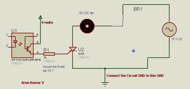
now that i am using 15vDC power supply would the circuit look like this below
and the triac in the diagram is BT136 which i can find but which one is the optocoupler model.
i also noticed that u said that the led part of the optocoupler should be connected in the same way as it was with the moc3011. but in moc3011 on the left hand side, the upper pin(pin1) is going to 5v dc and the lower pin2 one going to port22 of 8051. pin6 into triac and pin4 into resistor.
but in optocoupler pin4 is connected to the resistor which is connected to triac and pin5 is connected to 5v DC. and im assuming the pin2 is going into port22 of 8051 and pin1 to 5v dc if i am right ?
![]()
thanks for making it very simple for ppl like me to understand....really appreciated it. but 1 little question just to make sure i got it right..
now that i am using 15vDC power supply would the circuit look like this below
and the triac in the diagram is BT136 which i can find but which one is the optocoupler model.
i also noticed that u said that the led part of the optocoupler should be connected in the same way as it was with the moc3011. but in moc3011 on the left hand side, the upper pin(pin1) is going to 5v dc and the lower pin2 one going to port22 of 8051. pin6 into triac and pin4 into resistor.
but in optocoupler pin4 is connected to the resistor which is connected to triac and pin5 is connected to 5v DC. and im assuming the pin2 is going into port22 of 8051 and pin1 to 5v dc if i am right ?


Sat Dec 06 2008, 07:39 am
digital guy, you can use any general opto like : PC817, MCT2E, 4N25, ........ etc if you have any other opto on hand then search for its datasheet to know its pin out.
pin out of MOC3011/21/41 etc are different from other optos so don't be rigid on pin numbers.
opto connections: ( for any optocoupler)
LED side : Anode to + 5Vdc, cathode to pin 22 of micro thru series resistor 330ohms.
transistor side : collector to +5dc, emitter to gate of SCR/Triac/transistor/mosfet thru a series resistor of 1 K.
don't forget to connect GND of your 15 Vdc and 5 Vdc supply together ( if there are derived from separate sources)
it cannot be more simpler than this, i hope
Arun
digital-guy like this.
Mon Dec 08 2008, 12:31 am
hi arun
thanks for making it soo much easier for me to understand :-)
i was just wondering if the assembly code for the circuit will be the same for the circuit with moc3011 and 203V ac power supply at (http://www.8051projects.net/downloads170.html) and it will work in the same way and have the same features.
Fri Dec 19 2008, 05:30 pm
hi every1
i just wanted to ask something about the 7 segment led display that i am using
i am using dual digit 7segment " kingsbright DA56-11SRWA". it has 18 pins 9 on top and 9 on bottom
i just wanted to ask how i should connect it in the same way as the diagram below. there are no pin letters ( a,b,c etc) and there seem to be no dp pin as only 7 lines from microcontroller are used. i am using a breadboard.
your help would be much appreciated
thankyou
![]()
i just wanted to ask something about the 7 segment led display that i am using
i am using dual digit 7segment " kingsbright DA56-11SRWA". it has 18 pins 9 on top and 9 on bottom
i just wanted to ask how i should connect it in the same way as the diagram below. there are no pin letters ( a,b,c etc) and there seem to be no dp pin as only 7 lines from microcontroller are used. i am using a breadboard.
your help would be much appreciated
thankyou
Fri Dec 19 2008, 07:29 pm
Hello Digital-Guy,
in the above schematic the multiplexed seven segment LED display is connected to Port0, about the connections- port0.0 is connected to segment "a", port0.1 to "b"...... so on upto port0.6 which is connected to "g". since the dp is not used port0.7 is left unconnected.
its always better to use pull-up resistors for port0 which are obviously missing in the above circuit.
and here's datasheet of the LED display is you don't have it
Arun
Mon Dec 29 2008, 07:56 pm
hi arun
this part of the circuit is attached to port 13 of the 8051. and if i am not mistaken it just converts 230V ac into 5v dc. since i wont need this part as im already using a power supply that can produce 5, 12 and 15 v dc. so do i just connect 5v dc into port 13 of microcontroller??
![]()
this part of the circuit is attached to port 13 of the 8051. and if i am not mistaken it just converts 230V ac into 5v dc. since i wont need this part as im already using a power supply that can produce 5, 12 and 15 v dc. so do i just connect 5v dc into port 13 of microcontroller??
Mon Dec 29 2008, 08:07 pm
Hello Digital Guy,
if i am not mistaken it just converts 230V ac into 5v dc. since i wont need this part as im already using a power supply that can produce 5, 12 and 15 v dc. so do i just connect 5v dc into port 13 of microcontroller??
No, its not just mere Power supply but its also a ZERO CROSS Detector circuitry built around dual OP-AMP which sends square wave pulse to micro at pin 13, so that the micro knows when it can "fire" the Triac.
Arun
Mon Dec 29 2008, 08:28 pm
hi again arun
so i dont really need it for everything to function properly...right?
and the other thing is that the 7 seg dual display has 18 pins, like shown below.
can i connect all the a,b,c,d....g's togather for both dual 7 segments except the connections going to the transistor. and are the connections going to the transistors are as shown below??? or is it a different pin of 7 seg?? in other words are the first 8 pins are as follows; a b c d e f g dp and transistor pin and the same for the 9 pins below for the same dual 7 seg led display.(common anode). and the pins that do go to the transistor, do they go into the emitter of the transistor?
![]()
so i dont really need it for everything to function properly...right?
and the other thing is that the 7 seg dual display has 18 pins, like shown below.
can i connect all the a,b,c,d....g's togather for both dual 7 segments except the connections going to the transistor. and are the connections going to the transistors are as shown below??? or is it a different pin of 7 seg?? in other words are the first 8 pins are as follows; a b c d e f g dp and transistor pin and the same for the 9 pins below for the same dual 7 seg led display.(common anode). and the pins that do go to the transistor, do they go into the emitter of the transistor?

[ Edited Mon Dec 29 2008, 08:32 pm ]

Mon Dec 29 2008, 10:09 pm
The datasheet has a different pinout than you've posted.... like pin1 is 'e',pin2 is 'd' etc.
hope you're following the correct pinout.
Pins 14 and 13 are the common anode pins of the 2 displays and connect to the emitters of the transistors as shown in your schematic.
And yes you may connect the respective a,b,c.. segments of both displays.
![]()
hope you're following the correct pinout.
Pins 14 and 13 are the common anode pins of the 2 displays and connect to the emitters of the transistors as shown in your schematic.
And yes you may connect the respective a,b,c.. segments of both displays.
Tue Dec 30 2008, 01:02 am
hi sashijoseph
does this mean that the connections would look like this.?
sorry about this....i just like to visualise everything before making it final
![]()
does this mean that the connections would look like this.?
sorry about this....i just like to visualise everything before making it final

Powered by e107 Forum System

KevinTab
Sun Apr 28 2024, 05:35 am

Tumergix
Sun Apr 28 2024, 12:59 am

StevenDrulk
Sat Apr 27 2024, 08:47 pm

StephenHauct
Sat Apr 27 2024, 09:38 am

Adamsaf
Sat Apr 27 2024, 07:12 am

Robertphype
Sat Apr 27 2024, 12:23 am

ktaletrryp
Fri Apr 26 2024, 10:55 pm

Robertrip
Fri Apr 26 2024, 11:20 am