Help with temp. control fan hardware


Mon Feb 09 2009, 08:34 pm
digital -guy, you are lucky that you are posting your doubts in our forum, if you would have posted your doubts in some other forum, i think the people there would ask you to go and learn basic electronics and then try using Micros.
i had clearly explained in my above posts how you have to set the things with help of diagrams, i had asked to connect the diode across the motor, now in your diagram where have you connected it - in series with motor, and with this set up do you think the motor will work - the current passing thru motor will be blocked by the diode and will never reach the drain of mosfet.
now in all these pages of the post we have talking about pin22 of the micro, and in the last post too i have been time and again mentioning about the pin22 nad 10K pullup resistor.
anyway, here is the diagram;
![]()
Arun
i had clearly explained in my above posts how you have to set the things with help of diagrams, i had asked to connect the diode across the motor, now in your diagram where have you connected it - in series with motor, and with this set up do you think the motor will work - the current passing thru motor will be blocked by the diode and will never reach the drain of mosfet.
now in all these pages of the post we have talking about pin22 of the micro, and in the last post too i have been time and again mentioning about the pin22 nad 10K pullup resistor.
anyway, here is the diagram;

Arun
digital-guy like this.


Mon Feb 09 2009, 08:53 pm
hi arun
i cant thank u enough for all the help and support you have given me so far... i really appreciate it. i hope this will in future help ppl like me to understand the concepts...
so i understand that the hardware is now complete...
since i'm starting with a code for a 230v ac fan with zero crossing detector...how will i need to modify it and use with current hardware
PS: is there any program that converts assembly code into C language or vise versa and just to confirm...i can program 8051 in c rite?
[ Edited Tue Feb 10 2009, 05:16 am ]
Tue Feb 10 2009, 07:55 am
PS: is there any program that converts assembly code into C language or vise versa and just to confirm...i can program 8051 in c rite?
there are some applications which convert assembly code into C code but they are too expensive and not advisable. here's one such software :
http://www.textmaestro.com/InfoEx_17_Convert_Assembly.htm
you can write program in C for 8051( for that matter any micro).
Arun
Wed Feb 11 2009, 01:35 am
i was wondering if i can program the uC in c and assembly at the same time... e.g. code for lcd and buttons in c and the rest in assembly ? if yes then how would i do it before i convert it into hex.
Tue Feb 24 2009, 03:35 am
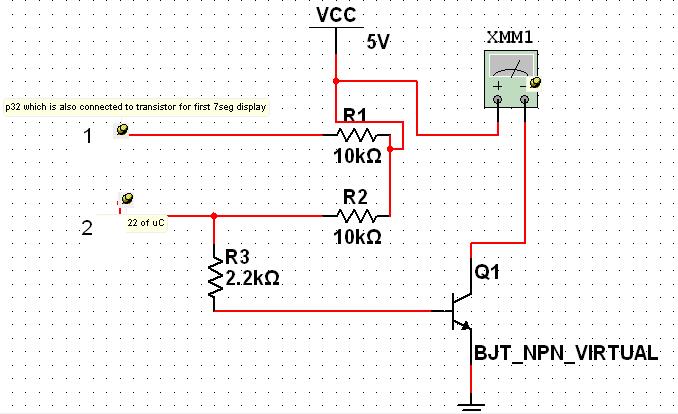
i have a question that i cant seem to find an answer to... when i connect my circuit in the following way...i dont know if u can see but connection 1 goes to p32 of uC and is also connected to the transistor for the 1st 7seg display
connection 2 goes to p22 of uC.
each time the temperature goes beyond the 24 degrees... the fan is suppose to turn on. and if i measure the voltage connected in the same way as above... it only gives me about 1.4V and if i measure the voltage from the collector with respect to ground it only gives me 10mV and if i connect one end of multimeter to collecor and the other to 12V...it only gives me about 3.23... V (i have used a bc547 and tip122darlington n channel)...why am i getting so low voltage???...i cant even move a little 5v fan with this configurations.
![]()
connection 2 goes to p22 of uC.
each time the temperature goes beyond the 24 degrees... the fan is suppose to turn on. and if i measure the voltage connected in the same way as above... it only gives me about 1.4V and if i measure the voltage from the collector with respect to ground it only gives me 10mV and if i connect one end of multimeter to collecor and the other to 12V...it only gives me about 3.23... V (i have used a bc547 and tip122darlington n channel)...why am i getting so low voltage???...i cant even move a little 5v fan with this configurations.


Tue Feb 24 2009, 05:47 am
i was wondering if i can program the uC in c and assembly at the same time... e.g. code for lcd and buttons in c and the rest in assembly ? if yes then how would i do it before i convert it into hex.
Yes you can. Most compilers use the keyword "asm" to allow you to insert assembly blocks
as in this made up snippet.
asm
{
add a,1
mov b,a
}
FET transistors need virtually no current to operate so the a 10k resistor is fine.
bc547 and tip122 and not FETs and need much more current to operate.
Change R2 to 1K, use a TIP122 and see what happens.
That said, your circuit should be able drive the meter to show 4.8 volts
when fully on, but you will only get that when the temperature is well above
the set point.
One possibility is that you have not connected the transistor correctly
check the pin connections again.. and again

[ Edited Tue Feb 24 2009, 05:57 am ]
Tue Feb 24 2009, 09:18 am
(i have used a bc547 and tip122darlington n channel)
No, you haven't used an N channel mosfet, what your schematic shows is a NPN transistor and the VCC is 5V not 12V as you claim in your post.
Arun
Wed Feb 25 2009, 06:17 am
hi arun
i'm sorry that my schematic shows a normal npn transistor...i just put it there as i have used 2 different transistors like bc547 and tip122.
and ExperimenterUK... i have checked my connections and tried R2 as 1k but it turns off the 2nd 7seg as r1(connected with transistor for 2nd 7seg) and r2 have a joint connection to 5V at that point...
i have had more success with using a relay... and it does trigger when the temp goes higher than the limit and gives me around 4.5v on multimeter when i connect the output of relay with respect to +5v... but when i connect the 5v fan....everything just goes off like it is short circuited... :mad
Fri Feb 27 2009, 01:11 am
i have checked my connections and tried R2 as 1k but it turns off the 2nd 7seg as r1(connected with transistor for 2nd 7seg) and r2 have a joint connection to 5V at that point...digital-guy
If your circuit is wired as in the diagram the 2nd 7seg will not be affected.
I suspect you have a bad connection somewhere, so that the R1-R2 junction is not
connected to 5 volts.
Or perhaps your supply is weak.
While testing, write a simple program that just turns on pin 22.
[ Edited Fri Feb 27 2009, 05:32 am ]
digital-guy like this.
Sat Mar 07 2009, 09:46 pm
thankyou all for helping me soo much to finish the hardware. at the moment i have a program for the 8051 that only makes the fan run at 1 speed. for example if the temperature goes above the limit the fan turns on and stays on until the room temp goes below the limit. what i want is with the help of pwm add fan 4 fan speeds e.g.
1/4 power, 1/2,3/4 and 4/4 power in such a way that when:
current temp = set temp then its 1/4 power is applied
current temp - set temp = 1 then its 1/2 power
c temp - s temp = 2 its 3/4 and anything above it the fan is on full speed.
i cant seem to figure out what is wrong with the code
here is the code to make the fan run at 1/2 power
; MOV A,NUMB3 ; stored temp
;MOV B, R3 ;room temp
;CJNE A, B, TWO
;SETB ALARM ; fan does turn on when equal but doesnt when incremented
; JMP EDE
;TWO: MOV A, NUMB3
;INC A
;MOV B, R3
;CJNE A, B, THRE
;SETB ALARM
;MOV R5, #25
;ACALL DLAYY
;CLR ALARM
;MOV R5, #75
;ACALL DLAYY
;DLAYY:
;H1: MOV R2, #100
;H2: MOV R3, #255
;H3: DJNZ R3, H3
;DJNZ R2, H2
;DJNZ R5, H1
;RET
please point me to the right direction :-s
Powered by e107 Forum System

StevenDrulk
Sat Apr 27 2024, 08:47 pm

StephenHauct
Sat Apr 27 2024, 09:38 am

Adamsaf
Sat Apr 27 2024, 07:12 am

Robertphype
Sat Apr 27 2024, 12:23 am

ktaletrryp
Fri Apr 26 2024, 10:55 pm

Robertrip
Fri Apr 26 2024, 11:20 am

ArnoldDiant
Fri Apr 26 2024, 03:53 am

RodneyKnorb
Thu Apr 25 2024, 07:08 pm