[SOLVED]No output on LCD screen of green bee project.


Mon Mar 23 2009, 03:18 am
chinmay, i will take a look at this tomorrow, coz ur problem need serious attention and i am running out of time. tomorrow is my office and its already 3:20am 
hope u dont mind waiting few more hours..
hope u dont mind waiting few more hours..


Tue Mar 24 2009, 12:11 am
[conversation at chat box ]
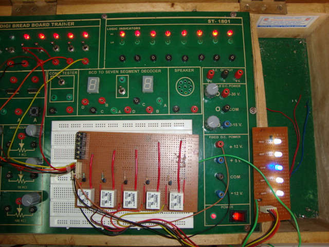
chinmay:well i hv connected 5 LEDs as indicator for actuator.if any actuator get active den its corresponding LED will glow.bt i found dat Dos leds r glowing wid very less intensity,means de r nt glowing brightly. bt when i tried d relay ckt on bread board n gave 5vdc de glow brightly.it seems o/p current 4m uC is very less. I tested every actuator port n found d o/p voltage is abt 4.86V n itz more dan sufficient 2 glow a LED brightly.bt still i m nt getting it. now give a look 2 dis pic...
![]()
ricky17:if the sensor input id in extreme case then the output of sensor will be in the 4 to 5 volts range which is converted by adc and given to the uc.uc compares with extreme cases stored in it and if it is that range then uc will on the respective actuator .voltage is controlled by input of adc,so try something in extreme case then see the output. if voltage is low at ADC , respective o/p at actuator port will b low. Low voltage means low current. if low current is given 2 base of the transistor of relay ckt, den definitely ur led will glow less. so check the current at the base of transistor.
chinmay:well i hv connected 5 LEDs as indicator for actuator.if any actuator get active den its corresponding LED will glow.bt i found dat Dos leds r glowing wid very less intensity,means de r nt glowing brightly. bt when i tried d relay ckt on bread board n gave 5vdc de glow brightly.it seems o/p current 4m uC is very less. I tested every actuator port n found d o/p voltage is abt 4.86V n itz more dan sufficient 2 glow a LED brightly.bt still i m nt getting it. now give a look 2 dis pic...
ricky17:if the sensor input id in extreme case then the output of sensor will be in the 4 to 5 volts range which is converted by adc and given to the uc.uc compares with extreme cases stored in it and if it is that range then uc will on the respective actuator .voltage is controlled by input of adc,so try something in extreme case then see the output. if voltage is low at ADC , respective o/p at actuator port will b low. Low voltage means low current. if low current is given 2 base of the transistor of relay ckt, den definitely ur led will glow less. so check the current at the base of transistor.
[ Edited Tue Mar 24 2009, 12:54 am ]
Tue Mar 24 2009, 03:50 pm
ricky17 you have pointed the right mistake. I have made some changes to the program by adding the wait condition for End of conversion. Just give it a try see if you get some stablity in system or not.
adcread:			;Initializing ADC
	;SENSOR 1
	MOV ADCDATA, #0FFH      ; Data lines for input

	SETB EOC		; Make EOC i/p
	CLR ALE		 ; clearing ALE
	CLR START	       ; Make start high
	CLR OE		  ; Disable o/p

	CLR ADD_A	       ;A=0
	CLR ADD_B	       ;B=0    ;Select IN4
	;CLR ADD_C	      ;C=0 (select IN0)
	ACALL delay
	SETB ALE		;latching the address
	ACALL delay
	SETB START	      ;start conversion pulse
	ACALL delay
	CLR ALE		 ;ALE H-L transition
	CLR START	       ;START H-L transition

	;Wait for end of conversion
	jb EOC,$

	SETB OE		 ;enable o/p
	ACALL delay	     ;

	MOV T_BUFFER, ADCDATA   ;store adc data to buffer
	CLR OE		  ;disable o/p

	;SENSOR 2
	MOV ADCDATA, #0FFH      ; Data lines for input

	SETB EOC		; Make EOC i/p
	CLR ALE		 ; clearing ALE
	CLR START	       ; Make start high
	CLR OE		  ; Disable o/p

	SETB ADD_A	      ;A=1
	CLR ADD_B	       ;B=0    Select IN5
	;CLR ADD_C	      ;C=0 (select IN0)
	ACALL delay
	SETB ALE		;latching the address
	ACALL delay
	SETB START	      ;start conversion pulse
	ACALL delay
	CLR ALE		 ;ALE H-L transition
	CLR START	       ;START H-L transition

	;Wait for end of conversion
	jb EOC,$

	SETB OE		 ;enable o/p
	ACALL delay	     ;

	MOV M_BUFFER, ADCDATA   ;store adc data to buffer
	CLR OE		  ;disable o/p

	;SENSOR 3
	MOV ADCDATA, #0FFH      ; Data lines for input

	SETB EOC		; Make EOC i/p
	CLR ALE		 ; clearing ALE
	CLR START	       ; Make start high
	CLR OE		  ; Disable o/p

	CLR ADD_A	       ;A=0
	SETB ADD_B	      ;B=1    Select IN6
	;CLR ADD_C	      ;C=0 (select IN0)
	ACALL delay
	SETB ALE		;latching the address
	ACALL delay
	SETB START	      ;start conversion pulse
	ACALL delay
	CLR ALE		 ;ALE H-L transition
	CLR START	       ;START H-L transition

	;Wait for end of conversion
	jb EOC,$

	SETB OE		 ;enable o/p
	ACALL delay	     ;

	MOV RH_BUFFER, ADCDATA  ;store adc data to buffer
	CLR OE		  ;disable o/p

	;SENSOR 4
	MOV ADCDATA, #0FFH      ; Data lines for input

	SETB EOC		; Make EOC i/p
	CLR ALE		 ; clearing ALE
	CLR START	       ; Make start high
	CLR OE		  ; Disable o/p

	SETB ADD_A	      ;A=1
	SETB ADD_B	      ;B=1    Select IN7
	;CLR ADD_C	      ;C=0 (select IN0)
	ACALL delay
	SETB ALE		;latching the address
	ACALL delay
	SETB START	      ;start conversion pulse
	ACALL delay
	CLR ALE		 ;ALE H-L transition
	CLR START	       ;START H-L transition

	;Wait for end of conversion
	jb EOC,$

	SETB OE		 ;enable o/p
	ACALL delay	     ;

	MOV L_BUFFER, ADCDATA   ;store adc data to buffer
	CLR OE		  ;disable o/p


	RET
Chinmay Das like this.
Tue Mar 24 2009, 03:54 pm
Its not recommended to drive LEDs directly from port as 8051 port pins are not capable of providing sufficient current to the LED. its is recommended to use port pins are sinking point rather than sourcing for LEDs.
i.e. LED should be connected like this..
PortPin ----|<|----/\/\/\-----| VCC
so LEDs will now be driven in -ve logic, which means 0 is ON and 1 is OFF. use resistance of about 680ohm increase if circuit is using more current then increase this resistance value. increasing resistance will reduce LED brightness a little.
Chinmay Das like this.

Tue Mar 24 2009, 04:34 pm
CHECK THIS SIR
adcread: ;Initializing ADC
;SENSOR 1
MOV ADCDATA, #0FFH ; Data lines for input
SETB EOC ; Make EOC i/p
CLR ALE ; clearing ALE
CLR START ; Make start high
CLR OE ; Disable o/p
CLR ADD_A ;A=0
CLR ADD_B ;B=0 ;Select IN4
ACALL delay
SETB ALE ;latching the address
ACALL delay
SETB START ;start conversion pulse
ACALL delay
CLR ALE ;ALE H-L transition
CLR START ;START H-L transition
JB EOC,$ ;MONITOR EOC TO SEE IF CONVERSION
JNB EOC,$ ;IS FINISHED
SETB OE ;enable o/p
ACALL delay
MOV T_BUFFER, ADCDATA ;store adc data to buffer
CLR OE ;disable o/p
;SENSOR 2
MOV ADCDATA, #0FFH ; Data lines for input
SETB EOC ; Make EOC i/p
CLR ALE ; clearing ALE
CLR START ; Make start high
CLR OE ; Disable o/p
SETB ADD_A ;A=1
CLR ADD_B ;B=0 Select IN5
ACALL delay
SETB ALE ;latching the address
ACALL delay
SETB START ;start conversion pulse
ACALL delay
CLR ALE ;ALE H-L transition
CLR START ;START H-L transition
JB EOC,$ ;MONITOR EOC TO SEE IF CONVERSION
JNB EOC,$ ;IS FINISHED
SETB OE ;enable o/p
ACALL delay ;
MOV M_BUFFER, ADCDATA ;store adc data to buffer
CLR OE ;disable o/p
;SENSOR 3
MOV ADCDATA, #0FFH ; Data lines for input
SETB EOC ; Make EOC i/p
CLR ALE ; clearing ALE
CLR START ; Make start high
CLR OE ; Disable o/p
CLR ADD_A ;A=0
SETB ADD_B ;B=1 Select IN6
ACALL delay
SETB ALE ;latching the address
ACALL delay
SETB START ;start conversion pulse
ACALL delay
CLR ALE ;ALE H-L transition
CLR START ;START H-L transition
JB EOC,$ ;MONITOR EOC TO SEE IF CONVERSION
JNB EOC,$ ;IS FINISHED
SETB OE ;enable o/p
ACALL delay ;
MOV RH_BUFFER, ADCDATA ;store adc data to buffer
CLR OE ;disable o/p
;SENSOR 4
MOV ADCDATA, #0FFH ; Data lines for input
SETB EOC ; Make EOC i/p
CLR ALE ; clearing ALE
CLR START ; Make start high
CLR OE ; Disable o/p
SETB ADD_A ;A=1
SETB ADD_B ;B=1 Select IN7
ACALL delay
SETB ALE ;latching the address
ACALL delay
SETB START ;start conversion pulse
ACALL delay
CLR ALE ;ALE H-L transition
CLR START ;START H-L transition
JB EOC,$ ;MONITOR EOC TO SEE IF CONVERSION
JNB EOC,$ ;IS FINISHED
SETB OE ;enable o/p
ACALL delay ;
MOV L_BUFFER, ADCDATA ;store adc data to buffer
CLR OE ;disable o/p
RET
delay: ;Delay subroutine
MOV R3, #250
here1:
MOV R4, #255
here:
DJNZ R4, here
DJNZ R3, here1
RET
Tue Mar 24 2009, 05:02 pm
try both the codes.. i just don't recommend using too many wait loops as it may cause your program to stuck sometime in future. cannot guarantee but this happens.
if my code works then use it.
if my code works then use it.
Tue Mar 24 2009, 11:05 pm
hello ricky17
itz another good day 4 me . finaly ur codes work, now i can see letter "C" in actuator status msg.
Ajay , u caught d exact pt, the port pins are drawing current 4m relay ckt. i hv connected LEDs with relay lik dis...
![]()
and found dat V across the LED is 0.6V whn de r connected wid uC port pins. and if i connect it 2 bread board the V is 3.57V. it clearly indicates dat port pins r drawing current 4m relay ckt. and to over com this , i think ,i sud connect all actuator port pins wid Vcc tro a RNW..... Is dat an good idea ?bt i m nt sure which value reg sud i use 10k or 1k ? bt i m afraid if i connect no of port pins ( 10 port pin 4 LCD, 5 port pins 4 actuator, 1 to LED, 1 to RST) to Vcc, den may be uC won't get sufficient voltage.... :-s
itz another good day 4 me
. finaly ur codes work, now i can see letter "C" in actuator status msg. Ajay , u caught d exact pt, the port pins are drawing current 4m relay ckt. i hv connected LEDs with relay lik dis...

and found dat V across the LED is 0.6V whn de r connected wid uC port pins. and if i connect it 2 bread board the V is 3.57V. it clearly indicates dat port pins r drawing current 4m relay ckt. and to over com this , i think ,i sud connect all actuator port pins wid Vcc tro a RNW..... Is dat an good idea ?bt i m nt sure which value reg sud i use 10k or 1k
? bt i m afraid if i connect no of port pins ( 10 port pin 4 LCD, 5 port pins 4 actuator, 1 to LED, 1 to RST) to Vcc, den may be uC won't get sufficient voltage.... :-s Tue Mar 24 2009, 11:15 pm
Thanks Ajay
for adding necessary inst to adc read codes....i will chk it n burn on uC 2moro, den i will reply...any ways i got Logo 4 my project... here it itz...
![]()
for adding necessary inst to adc read codes....i will chk it n burn on uC 2moro, den i will reply...any ways i got Logo 4 my project... here it itz...

Wed Mar 25 2009, 01:55 am
hello Ajay n Ricky17
here r the new chked n modifed codes. from now onwards pls follow the dees codes only...itz checked , compiled n debugged in kiel. no more errors.. but not tested on uCs yet... pls do ur research on dis codes only.
thank you.
here r the new chked n modifed codes. from now onwards pls follow the dees codes only...itz checked , compiled n debugged in kiel. no more errors.. but not tested on uCs yet... pls do ur research on dis codes only.
thank you.
[ Edited Wed Mar 25 2009, 01:55 am ]
Thu Mar 26 2009, 09:28 am
Hello Ajay n Ricky17
Now i hv som good n bad news again. i run both the codes i.e 4m ajay n 4m ricky on uCs. both the codes ran successfully connecting all the sensors. I was able to see Temp, RH n LI reading for few sec but still getting the same variation in results of sensors data on LCD. but i found some thing interesting whn i constantly monitor the LDC reading for 2mins.. here my research results.
1. As u know cursor moves in every 5 sec, dats means uC update data in every 5 sec.
I noticed initially for 1st 10 sec it shows the exact room temp 29 C n RH :61% . but after dat it starts varing...
2. Then after 20-25 sec i again noticed whn RH is less than 5% on LCD , it shows the exact room temp on LCD and whn temp is less than 10 C on LCD , it shows the correct RH value on LCD i.e 60%. u can say the readings of Temp n RH on the LDC r varying inversely.
3. Then i give sufficient light 2 LDR. at fist (say for 5-15sec)my readings on LCD changed with the condition (shows Optimum cond), then again starts varying. Whn i closely monitored the temp n Light intensity reading on LDC i noticed dat LI reading is varying according to Temp readings. if the temp reading is in between T :8.0-17.0 C , the LI: Dim on LCD and for other dan dis value of temp it shows LI: Opt (optimum). and also during this entier process of LI, i never saw the actual room temp n RH. the variation range in between LI process is 0.00 C- 45.0 C. but whn i removed light 4m LDR ,i am able to see room temp again for few sec.
4. n during this entire monitoring of 2 mins i saw der is no variation in Soil moisture reading on LCD. it always shows SM: Excess, even if der is 0.00 V o/p in analog reading.
5. By adding a 10k VR in o/p of temp ckt , i m able to minimize the variation range in temp reading on LCD.
Conclusion
Though der is variations in readings but som how i was able see the exact value of temp , RH n LI for few sec . i think der sud be som change in time delay process of ADC n LCD.as i checked ADC delay is 5 tim higher dan LCD delay.
so here i need som expert advice Ajay. pls reply soon as i hv 2 submit my project next week.
thanks hv a gr8 day :-)
Now i hv som good n bad news again. i run both the codes i.e 4m ajay n 4m ricky on uCs. both the codes ran successfully connecting all the sensors. I was able to see Temp, RH n LI reading for few sec but still getting the same variation in results of sensors data on LCD. but i found some thing interesting whn i constantly monitor the LDC reading for 2mins.. here my research results.
1. As u know cursor moves in every 5 sec, dats means uC update data in every 5 sec.
I noticed initially for 1st 10 sec it shows the exact room temp 29 C n RH :61% . but after dat it starts varing...
2. Then after 20-25 sec i again noticed whn RH is less than 5% on LCD , it shows the exact room temp on LCD and whn temp is less than 10 C on LCD , it shows the correct RH value on LCD i.e 60%. u can say the readings of Temp n RH on the LDC r varying inversely.
3. Then i give sufficient light 2 LDR. at fist (say for 5-15sec)my readings on LCD changed with the condition (shows Optimum cond), then again starts varying. Whn i closely monitored the temp n Light intensity reading on LDC i noticed dat LI reading is varying according to Temp readings. if the temp reading is in between T :8.0-17.0 C , the LI: Dim on LCD and for other dan dis value of temp it shows LI: Opt (optimum). and also during this entier process of LI, i never saw the actual room temp n RH. the variation range in between LI process is 0.00 C- 45.0 C. but whn i removed light 4m LDR ,i am able to see room temp again for few sec.
4. n during this entire monitoring of 2 mins i saw der is no variation in Soil moisture reading on LCD. it always shows SM: Excess, even if der is 0.00 V o/p in analog reading.
5. By adding a 10k VR in o/p of temp ckt , i m able to minimize the variation range in temp reading on LCD.
Conclusion
Though der is variations in readings but som how i was able see the exact value of temp , RH n LI for few sec
. i think der sud be som change in time delay process of ADC n LCD.as i checked ADC delay is 5 tim higher dan LCD delay.so here i need som expert
advice Ajay. pls reply soon as i hv 2 submit my project next week. thanks hv a gr8 day :-)
Powered by e107 Forum System

KevinTab
Sun Apr 28 2024, 05:35 am

Tumergix
Sun Apr 28 2024, 12:59 am

StevenDrulk
Sat Apr 27 2024, 08:47 pm

StephenHauct
Sat Apr 27 2024, 09:38 am

Adamsaf
Sat Apr 27 2024, 07:12 am

Robertphype
Sat Apr 27 2024, 12:23 am

ktaletrryp
Fri Apr 26 2024, 10:55 pm

Robertrip
Fri Apr 26 2024, 11:20 am