changing this project (Data acquisition system using 8051) to another type of DAQ...need help


Fri Aug 12 2011, 09:26 pm
do u have circuit diagram for adc0804 and analog mux ic and if i change it does it mean i must change the keil programing for the at89s51....
it is simple just like an adc 0804
u has to share its one channel with other sensors using analog mux
mux ic has addresses
using controller coding u has to change its address noe mux connect that sensor to the adc0804 now read the value of adc
other logic i ssame ansd yes u need to change a little in code
not more just tune the adc routines along with mux addressing
the sensor is looking like a variable resistor strip that can be used in series to another resistor
if it is piezoelectric effect then also can be connected in series to a resistor like a mic connections
http://www.siddiq.com.np/circuits/clap_switch_files/image001.gif


Sat Aug 13 2011, 05:28 am
@ redzs08
u can refer to this code for adc0804
http://www.8051projects.net/download-d214-simple-digital-voltmeter-using-8051.html
do analog mux coding by urself
u can refer to this code for adc0804
http://www.8051projects.net/download-d214-simple-digital-voltmeter-using-8051.html
do analog mux coding by urself
Mon Aug 15 2011, 08:46 pm
@ majoka
the project work perfectly now...... the problem is, the delay was to short and it cause the reading to jump high and low.....
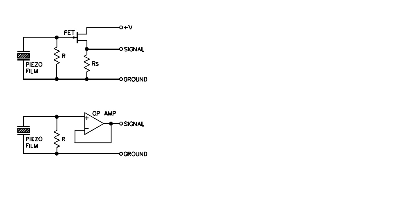
i have a circuit for piezo vibration can i use it ..... it will give analog signal can i use it without change the microcontroller code.........
![]()
the project work perfectly now...... the problem is, the delay was to short and it cause the reading to jump high and low.....
i have a circuit for piezo vibration can i use it ..... it will give analog signal can i use it without change the microcontroller code.........
[ Edited Mon Aug 15 2011, 08:47 pm ]
Mon Aug 15 2011, 09:29 pm
@ redzs08
in which code u want to merge
this has analog output as it can't interfaced directly to 8051
u need adc or op amp
it depend on ur application and ur need
in which code u want to merge
this has analog output as it can't interfaced directly to 8051
u need adc or op amp
it depend on ur application and ur need
Fri Aug 19 2011, 09:25 pm
is some have pcb layout for DAQ ..... cozs i'm getting wrong in routing .... 
Sun Aug 21 2011, 11:14 pm
how does this syntax work is to have some delay
pls some hlep.......
how to select what port in pc like com 1/2/3 the code from max232 will or doe it select the code automatically........
how does this syntax work i know roughly but can someone help explain it..
void usDelay(int a)
{
	TH0=256-(a/1.085);
	TR0=1;
	ET0=1;
}
pls some hlep.......
how to select what port in pc like com 1/2/3 the code from max232 will or doe it select the code automatically........
how does this syntax work i know roughly but can someone help explain it..
P1=(P1&0xf8)+sensor;
[ Edited Mon Aug 22 2011, 07:32 pm ]


Mon Aug 22 2011, 08:20 pm
void usDelay(int a)
{
        TH0=256-(a/1.085);
        TR0=1;
        ET0=1;
}
Yes this code is suppose to generate delay but i am afraid it will not be correct. reason being the involvement of floating point calculations. The following single statement itself will take most of the processing time before it actually generate some delay
TH0=256-(a/1.085);
i suggest you avoid such statements.
how to select what port in pc like com 1/2/3 the code from max232 will or doe it select the code automatically........
redzs08
I did not understand what exactly you're asking.
P1=(P1&0xf8)+sensor;
well it looks like you are using an 8 channel ADC or something.. the above code seems to set the select bit of ADC. statement is explained below..
P1 & 0xf8 = this part of statement actually clears the 3LSBs of Port 1. without touching the higher 5 bits.
if your port is set to 0x45 = 0b01000101
now 0x45 & 0xf8 (0b11111000) = 0x40
the lower 3 bits will be cleared.
after that this result is added to sensor (variable). e.g if your sensor value is 2 so
0x40 + 0x02 = 0x42
simple?

Mon Aug 22 2011, 08:37 pm
@ajay
thank for ur explanation it was easy 2 understand after u explain it.........
thank for ur explanation it was easy 2 understand after u explain it.........
Powered by e107 Forum System

KevinTab
Sun Apr 28 2024, 05:35 am

Tumergix
Sun Apr 28 2024, 12:59 am

StevenDrulk
Sat Apr 27 2024, 08:47 pm

StephenHauct
Sat Apr 27 2024, 09:38 am

Adamsaf
Sat Apr 27 2024, 07:12 am

Robertphype
Sat Apr 27 2024, 12:23 am

ktaletrryp
Fri Apr 26 2024, 10:55 pm

Robertrip
Fri Apr 26 2024, 11:20 am