[Solved]Project: Digital Room Thermometer using LM35 sensor and 8051 Microcontroller


Fri Apr 20 2012, 09:17 pm
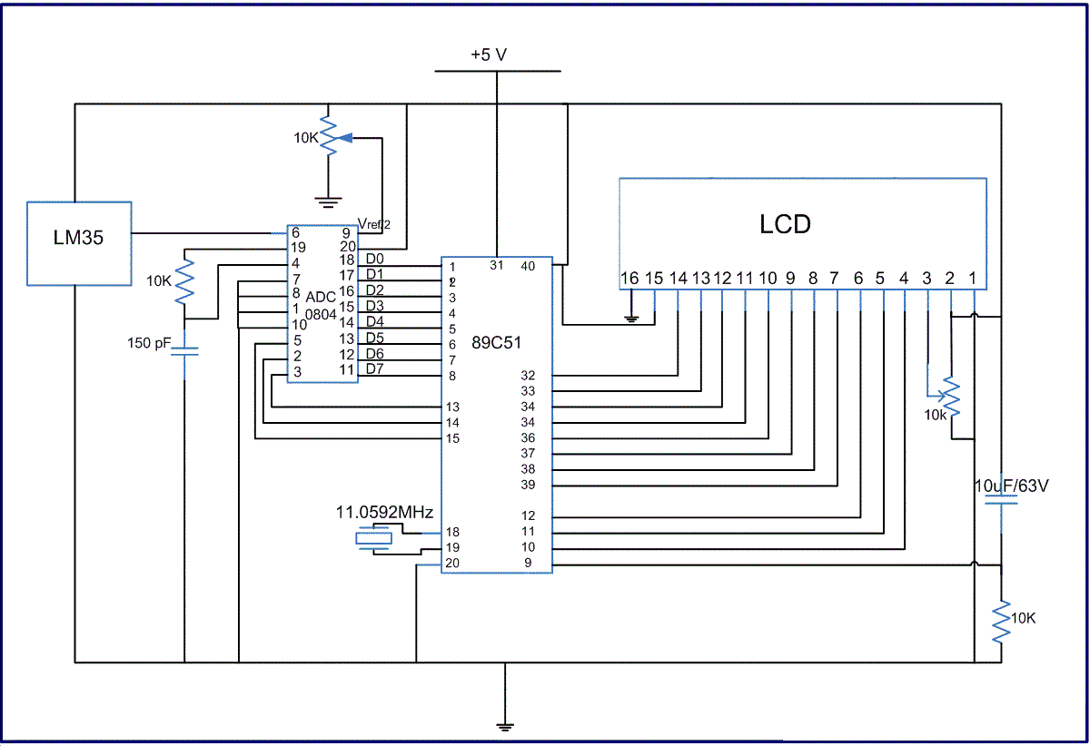
Sir, as today our burner didnt work , so we cant test that circuit. will test again tomorrow. mean while I need help also for completing our main project : digital room thermometer as our mentor are out of touch of these microcontroller and these things and it is too much to handle of our own . So, plz help. I am attaching circuit diagram here. At first , tell me the important things to test in order to start that project finally. We have tested
1) LM35 sensor simply by implying it in acircuit and varying temperature in one side and got satisfactory result.
2) tested ADC 0808 in free running mode and it is giving correct output. We kept reference voltage 1.28 volt so that the step size is in accordance with lm35 step size .
3) will test LCD initialization tomorrow .
tell other important things.
[ Edited Fri Apr 20 2012, 09:18 pm ]
Fri Apr 20 2012, 10:12 pm
next thing to test is ADC with microcontroller.. coz You will test your LCD so there will be a display to print your test results. You guys are going on the right track  good luck! let us know if you need any help.
good luck! let us know if you need any help. Fri Apr 20 2012, 10:19 pm
give us some ideas for how to test adc with microcontroller? what things we have to include in the c code ? then i can write it now and post here to verify .. will u plz rep. sooner? we have a deadline ahead sooner , so we have to grasp the concept and as well as programming. so, plz help
Fri Apr 20 2012, 10:26 pm
why dont you go through ADC tutorial? It has working example of ADC0804. Take a look here...
http://www.8051projects.net/adc-interfacing/
http://www.8051projects.net/adc-interfacing/
Fri Apr 20 2012, 10:39 pm
Thanx. very thorough tutorial . Now using that 8051 code, the output will be at microprocessor port 3 . . so , how can we read microprocessor output from port 3 ? do we have to use LCD alongwith microprocessor( connect LCD dataport to p3 of microprocessor) and adc to make it work or only microprocessor and adc can be used??
#include <REGX51.H>#define adc_port P2 //ADC Port
#define rd P1_0 //Read signal P1.0
#define wr P1_1 //Write signal P1.1
#define cs P1_2 //Chip Select P1.2
#define intr P1_3 //INTR signal P1.3
void conv(); //Start of conversion function
void read(); //Read ADC function
unsigned char adc_val;
void main(){
while(1){ //Forever loop
conv(); //Start conversion
read(); //Read ADC
P3 = adc_val; //Send the read value to P3
}
}
void conv(){
cs = 0; //Make CS low
wr = 0; //Make WR low
wr = 1; //Make WR high
cs = 1; //Make CS high
while(intr); //Wait for INTR to go low
}
void read(){
cs = 0; //Make CS low
rd = 0; //Make RD low
adc_val = adc_port; //Read ADC port
rd = 1; //Make RD high
cs = 1; //Make CS high
}
[ Edited Fri Apr 20 2012, 10:40 pm ]
Fri Apr 20 2012, 10:59 pm
Got your point . I am going to try to simulate LCD, microcontroller and ADC in proteus and accordingly modify the code. after some time, i will post the code and proteus schematic for your reference. And if that works too, we can test LCD and then adc interfacing microcontroller too tomorrow . . Posting it after sometime and Thanx
Powered by e107 Forum System

Clydehet
Wed May 01 2024, 06:44 pm

Davidoried
Wed May 01 2024, 06:11 pm

KevinTab
Sun Apr 28 2024, 05:35 am

Tumergix
Sun Apr 28 2024, 12:59 am

StevenDrulk
Sat Apr 27 2024, 08:47 pm

StephenHauct
Sat Apr 27 2024, 09:38 am

Adamsaf
Sat Apr 27 2024, 07:12 am

Robertphype
Sat Apr 27 2024, 12:23 am