[SOLVED] Help needed for making "Android Controlled robot"


1. Do i need to configure the module before using it in my project because i have made the hardware for the project but i am not able to run it. Whenever i touch/press the key on my phone nothing happens , motors don't move

2. The circuit diagram for the project don't show any resistors on port 2, but in the image of the real hardware of project, i appears there are resistors at the port 2. So do i actually need resistors at port 2?
3. Do you have the project Report file of this project, Please , need it in urgent .
Thanks in advance .
[ Edited Thu May 08 2014, 05:50 pm ]


2. They are not necessary as port 2 has internal pull-ups. But if you want you can connect pull-up on port pins. They won't harm.
3. No whatever was submitter by author is available for download.
a. How can I check if controller is toggling the GPIO?
b. Readings of multi-meter:
When no key pressed:
P3.0 = 0 v
P2.0 = 0 v
P2.1 = 0 v
P2.2 = 0 v
P2.3 = 0 v
P2.7 = 0 v
PIN 29 & 31 = 5.03 v
Bluetooth module:
State = 3.35 v when paired, ( 0 v when not paired)
RxD = 2.97 v
TxD = 0 v
Gnd = 0 v
Vcc = 4.88 v
Key = 0v
When Key Pressed:
P3.0 = 0 v
P2.0 = 0 v
P2.1 = 0 v
P2.2 = 0 v
P2.3 = 0 v
P2.7 = 0 v
PIN 29 & 31 = 5.03 v
Bluetooth module:
State =3.35 v when paired, ( 0 v when not paired)
RxD = 2.97 v
TxD = 0 v
Gnd = 0 v
Vcc = 4.88 v
Key = 0v
2. I have not connected resistors on PORT2 . I think, Its not creating any problem as you said its not mandatory.
3. Can you please ask the author if he had the Report file .
--Thanks
[ Edited Sat Apr 19 2014, 04:45 pm ]

Use your phone, or a PC with a bluetooth connection to send text of any sort to the module.
If it's working one of the LEDs will flash.
Connect the one that flashes to the 8051 rx pin.
Let us know how you get on.
I see that power to the module comes through R3 a dropper resistor.
I would change that to using a proper 3.3 volt regulator with a small (say 22uF ) smoothing cap.
Connect indicator LEDs, like those on status (32) and data (31) to the bluetooth tx and rx pins.
Use your phone, or a PC with a bluetooth connection to send text of any sort to the module.
If it's working one of the LEDs will flash.
Connect the one that flashes to the 8051 rx pin.
Let us know how you get on.
I see that power to the module comes through R3 a dropper resistor.
I would change that to using a proper 3.3 volt regulator with a small (say 22uF ) smoothing cap.ExperimenterUK
I am using this module : HC-05 JY-MCU, there is a status LED which glows at 2hz but when unpaired, when paired it glows at different frequency.
Controller Used
AT89S52
I am using this module : HC-05 JY-MCUjasmeet_singh
That version comes attached to an interface board with a built in regulator.
Connect power (J1 pin1) to 5 volts and remove D3 and R3.
The 6 pin connector on the project diagram does not have the same pin out as the
6 pin connector on your module. You will need to check which pins to connect.


another thing is that ur baud rate .... by default HC05 comes with 9600 baud rate .................so in order to test communication between mobile and bluetooth u can connect ur serial port of PC to 8051 demo board having MAX 232.......use FLASH MAGIC software terminal or any other serial terminal software and check whether u r able receive data at 9600 baud rate ? if u r getting random garbage value on terminal then there is problem with baud rate .............if not getting any data at all then u r mistaken with configuring terminal software
Here is my circuit Diagram.
Please check if something is wrong in it.
Bigger size
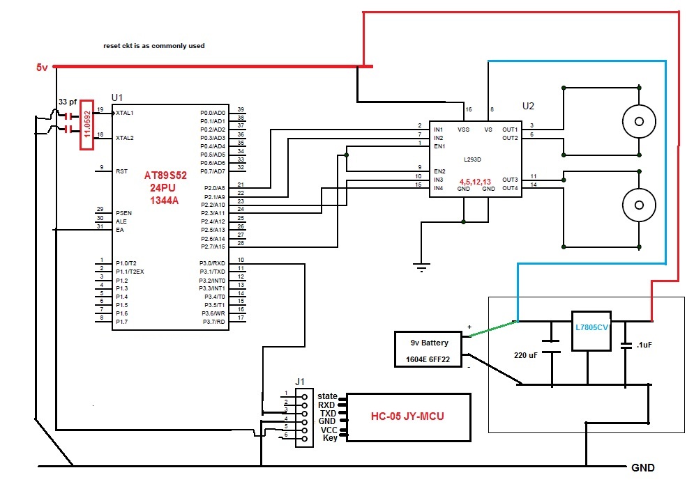
shouldn't you be connecting your controller's TXD pin with RX of HC-05? or is it just a one way communication that you're doing? You mentioned that keys are connected on P3. I do not see them. Where is the reset circuit for 8051? is it not shown or its not mounted at all? if not mounted then do it at first.ajay_bhargav
1. I think its like Mobile -> Bluetooth module -> controller -> Motor driver. So it requires only one way communication.
2. I didn't connected any Key to PORT3. P3.0 is Rxd Pin Also, there was no key in the original circuit. (In previous Posts "When Key pressed" Refers to the key on screen of the mobile)
3. Reset circuit as commonly used. Not shown here but is mounted.


