Urgent Help Needed for Bluetooth Controlled Robot


Fri May 09 2014, 04:51 pm
Its hard to say from a blur picture. If its pairing properly then module should be fine.. don't worry. You need to work on power supply section. I suggested you 3 LDOs did you check in market?

Sat May 10 2014, 03:10 am
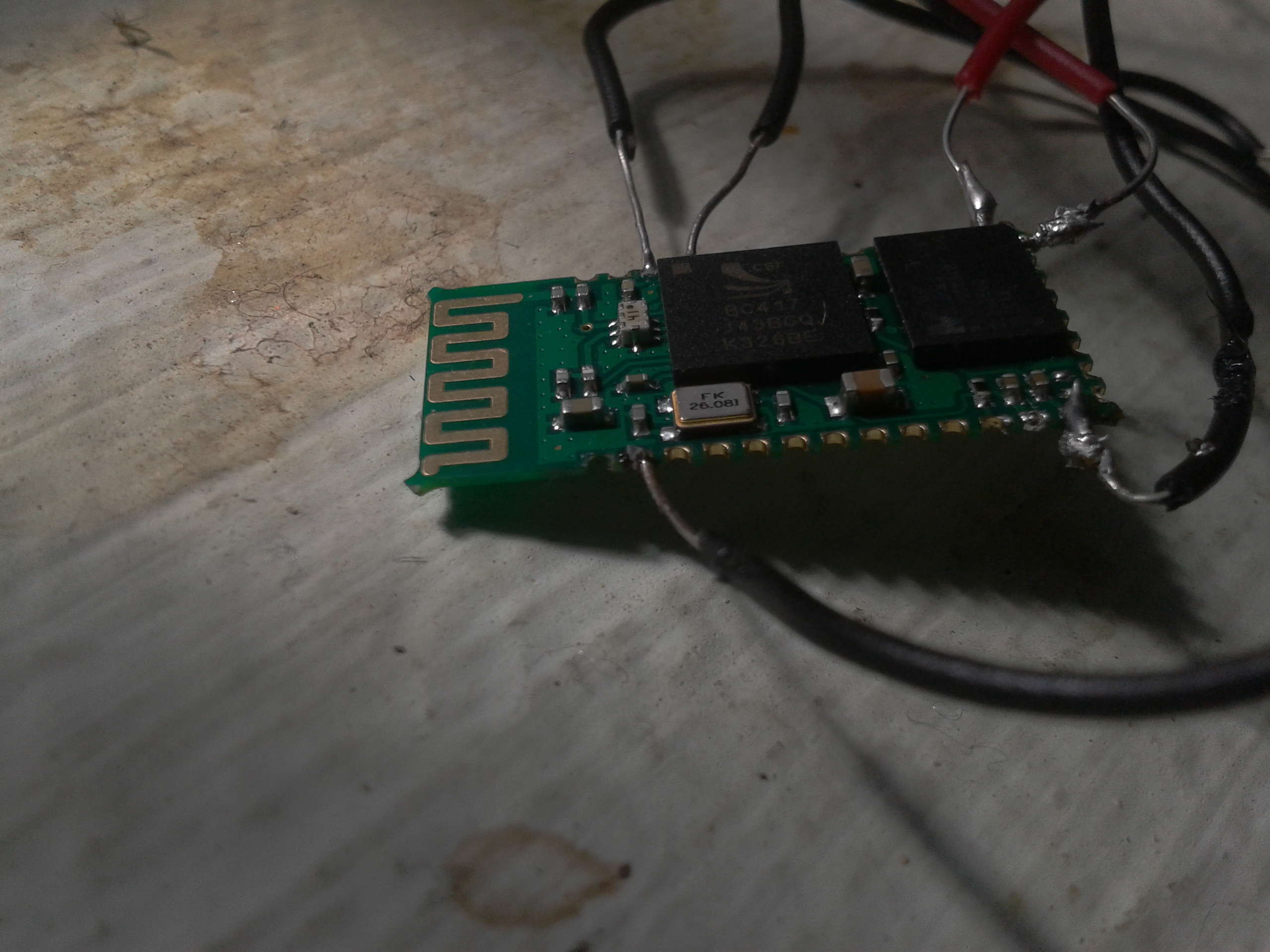
while soldering, the gold-coloured part from a pin fall off...
IS THIS A PROBLEM?amruthkiran
Pin 1 transmits data to the micro, so yes, it's a big problem !
It may just be that the joint has broken, leaving the gold in place but
discoloured... get a magnifying glass.
Using solid core wire puts a big stress on the joint, use thin multi strand in future.
now the problem is, i dont get a 3.3v supply. i only gets 1.74v from the regulator i bought(L7HL33).amruthkiran
You need to find out why you are getting a low voltage.
Is the regulator faulty ?
Have you wired it wrongly, or is the HC05 drawing too much current.?
Sat May 10 2014, 07:58 pm
here is a clearer image...i think its gone.. :-(
![]()
@experimenteruk i've the supply problem solved somehow.
@ajay so should i buy a new module?
i think this time i should buy module with base. if so, please give me a link of the same from which i can trust and buy.
@experimenteruk i've the supply problem solved somehow.
@ajay so should i buy a new module?
i think this time i should buy module with base. if so, please give me a link of the same from which i can trust and buy.
[ Edited Sat May 10 2014, 08:04 pm ]
Mon May 12 2014, 10:55 am
I would suggest you buy a new one. and please be careful with soldering in future. use a good ion, thin wires and less amount of solder so you can see what is going on. Dont keep the solder for too much time.
Here is the link I posted earlier too.
http://www.robomart.com/gps-gsm-rfid-bluetooth-module/hc-05-bluetooth-module-with-ttl.html
This module is used by Jasmeet (a member of our forum) So if you have any problems or need help you can also ask him. here is link to his post
Ref: http://www.8051projects.net/t63404/project-help/help-needed-for-quotandroid-controlled-robot-using-bluetoothquot.htm#post_63518
Tue May 13 2014, 05:34 pm
You can buy separate TTL base board and solder HC-05 module directly on to it. Here:
http://www.robomart.com/bluetooth-serial-transceiver-module-base-board-for-hc-06-hc-07-hc-05.html
http://www.robomart.com/bluetooth-serial-transceiver-module-base-board-for-hc-06-hc-07-hc-05.html
Wed May 14 2014, 11:37 am
ok, if i buy the base board, where i take the outputs from, i mean the outputs from its pins?
Thu May 15 2014, 10:21 am
Yes the pins shown on the right side of base board. They are properly labelled - RXD, TXD, KEY, VCC
Fri May 16 2014, 11:56 am
ok, im going to buy the base board.
1) what about the state and key pins on it? they are not present on it?
2) on connecting to a baseboard , the supply to hc-05 would be 5V. right?
3) i would also need soldering instructions while doing it on the base board.
1) what about the state and key pins on it? they are not present on it?
2) on connecting to a baseboard , the supply to hc-05 would be 5V. right?
3) i would also need soldering instructions while doing it on the base board.
Powered by e107 Forum System

JamesroW
Mon May 06 2024, 09:37 am

Chrispes
Mon May 06 2024, 07:34 am

ArktiTic
Sun May 05 2024, 07:06 pm

CesslasyNear
Sun May 05 2024, 02:58 pm

chimichmedic1204
Sun May 05 2024, 11:06 am

Jamiegob
Sun May 05 2024, 10:11 am

Gregoryjed
Sun May 05 2024, 10:02 am

Mariocax
Sun May 05 2024, 08:51 am